Rainbow Electronics MAX7036 User Manual
Page 6
MAX7036
300MHz to 450MHz ASK Receiver
with Internal IF Filter
6
_______________________________________________________________________________________
Pin Description
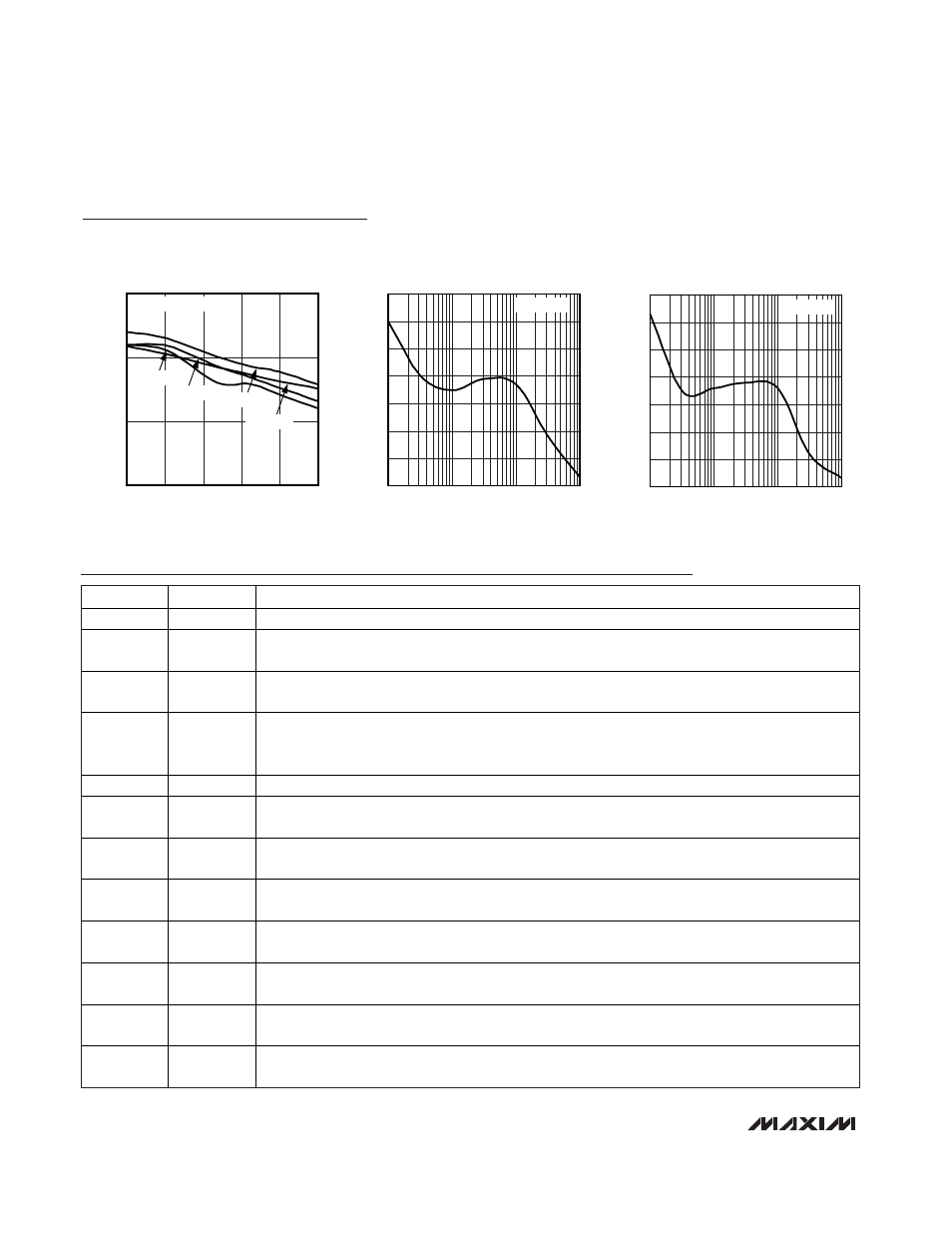
Typical Operating Characteristics (continued)
(
Typical Application Circuit, V
AVDD
= V
DD
= V
DVDD
= 3.3V, f
RF
= 315MHz, T
A
= +25°C, unless otherwise noted.)
PIN
NAME
FUNCTION
1
ENABLE
Enable Input. Internally pulled down to ground. Set V
ENABLE
= V
DD
for normal operation.
2
XTAL2
Crystal Input 2. Connect an external crystal from XTAL2 to XTAL1. Can also be driven with an AC-
coupled external reference oscillator (see the Crystal Oscillator section).
3
XTAL1
Crystal Input 1. Connect an external crystal from XTAL2 to XTAL1. Bypass to GND if XTAL2 is driven
from an AC-coupled external reference (see the Phase-Locked Loop section).
4
AVDD
Positive Analog Supply Voltage. Connect to DVDD. Bypass to GND with a 0.1µF capacitor as close as
possible to the device (see the Typical Application Circuit). For 5.0V operation, AVDD is internally
connected to an on-chip 3.2V LDO regulator. For 3.3V operation, connect AVDD to V
DD
.
5
LNAIN
Low-Noise Amplifier Input. Must be AC-coupled (see the Low-Noise Amplifier section).
6
LNAOUT
Low-Noise Amplifier Output. Must be connected to AVDD through a parallel LC tank circuit. AC-
couple to MIXIN2 (see the Low-Noise Amplifier section).
7
MIXIN2
2nd Differential Mixer Input. Connect to the LNAOUT side of the LC tank filter through a 100pF
capacitor (see the Typical Application Circuit).
8
MIXIN1
1st Differential Mixer Input. Connect to the AVDD side of the LC tank filter through a 100pF capacitor
(see the Typical Application Circuit).
9
IFC2
IF Fi l ter C ap aci tor C onnecti on 2. Thi s i s for the S al l en- Key IF fi l ter . C onnect a cap aci tor fr om IFC 2 to GN D .
The val ue of the cap aci tor i s d eter m i ned b y the IF fi l ter b and w i d th ( see the Typical Application Circuit) .
10
IFC1
IF Fi l ter C ap aci tor C onnecti on 1. Thi s i s for the S al l en- Key IF fi l ter . C onnect a cap aci tor fr om IFC 1 to IFC 3.
The val ue of the cap aci tor i s d eter m i ned b y the IF fi l ter b and w i d th ( see the Typical Application Circuit) .
11
IFC3
IF Fi l ter C ap aci tor C onnecti on 3. Thi s i s for the S al l en- Key IF fi l ter . C onnect a cap aci tor fr om IFC 3 to IFC 1.
The val ue of the cap aci tor i s d eter m i ned b y the IF fi l ter b and w i d th ( see the Typical Application Circuit) .
12
DVDD
Positive Digital Supply Voltage Input. Connect to AVDD. Bypass to GND with a 0.01µF capacitor as
close as possible to the device (see the Typical Application Circuit).
REGULATOR VOLTAGE
vs. REGULATOR CURRENT
MAX7036 toc10
REGULATOR CURRENT (mA)
REGULATOR VOLTAGE (V)
20
25
15
10
5
3.05
3.10
3.15
3.00
0
T
A
= -40
°C
T
A
= +25
°C
T
A
= +85
°C
T
A
= +105
°C
V
DD
= 5V, +5V CIRCUIT
PHASE NOISE vs. OFFSET FREQUENCY
MAX7036 toc11
OFFSET FREQUENCY (kHz)
PHASE NOISE (dBc/Hz)
100
10,000
1
-70
-60
-50
-120
-110
-100
-90
-80
0.01
f
RF
= 315MHz
PHASE NOISE vs. OFFSET FREQUENCY
MAX7036 toc12
OFFSET FREQUENCY (kHz)
PHASE NOISE (dBc/Hz)
100
10,000
1
-70
-60
-50
-120
-110
-100
-90
-80
0.01
f
RF
= 433MHz