Table 2. component values – Rainbow Electronics MAX7036 User Manual
Page 11
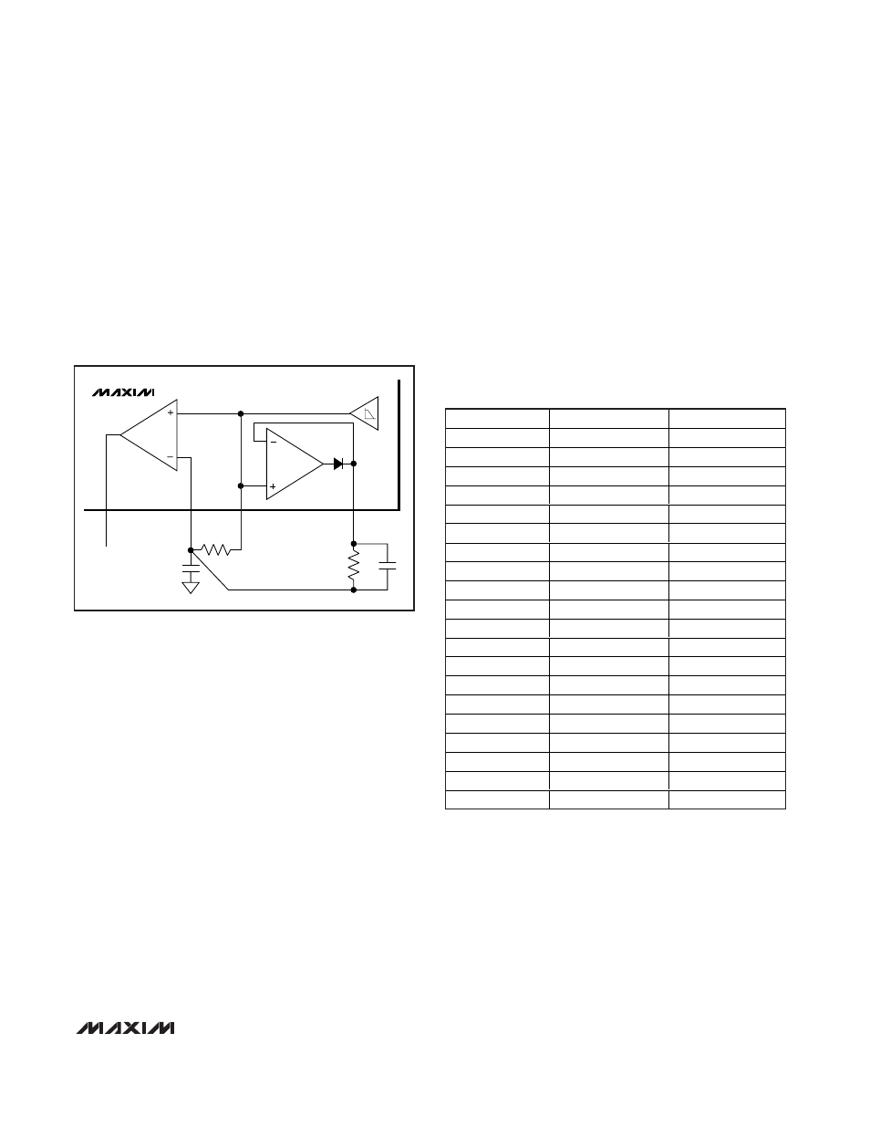
times larger than the resistor in the RC smoothing cir-
cuit between DSP and DSN. This circuit will provide an
instantaneous jump of one-half of the DSP increase
from “no signal” voltage to peak voltage, which then
decays with the same time constant as that of the
threshold build-up from the RC smoothing circuit. The
DC slicing voltage at DSN is slightly higher (by the ratio
of the two resistors in the circuit) than it would be with-
out the speed-up circuit. Always provide a capacitive
path from the PDOUT pin to ground when using the
peak-detector output.
Layout Considerations
A properly designed PCB is an essential part of any
RF/microwave circuit. On high-frequency inputs and
outputs, use controlled-impedance lines and keep them
as short as possible to minimize losses and radiation.
At high frequencies, trace lengths that are
λ/10 or
longer act as antennas.
Keeping the traces short also reduces parasitic induc-
tance. Generally, 1in of a PCB trace adds about 20nH
of parasitic inductance. The parasitic inductance can
have a dramatic effect on the effective inductance of a
passive component. For example, a 0.5in trace con-
necting a 100nH inductor adds an extra 10nH of induc-
tance or 10%.
To reduce the parasitic inductance, use wider traces
and a solid ground or power plane below the signal
traces. Also, use low-inductance connections to ground
on all GND pins, and place decoupling capacitors
close to all power-supply connections.
MAX7036
300MHz to 450MHz ASK Receiver
with Internal IF Filter
______________________________________________________________________________________
11
COMPONENT
f
RF
= 315MHz
f
RF
= 433.92MHz
C1
4.7pF
2.7pF
C2
100pF
100pF
C3
100pF
100pF
C4
0.1µF
0.1µF
C5
390pF
390pF
C6
180pF
180pF
C7
1µF
1µF
C8
0.01µF
0.01µF
C9
22pF
22pF
C10
10pF
10pF
C11
0.1µF
0.1µF
C12
220pF
220pF
C13
10pF
10pF
C14
10pF
10pF
C15
100pF
100pF
C16
0.1µF
0.1µF
L1
100nH
47nH
L2
27nH
15nH
R1
22k
Ω
22k
Ω
Y1
9.8375MHz
13.55375MHz
20
C4
R1
17
DSN
16
DSP
MAX7036
DATA OUT
DATA
SLICER
DATA
FILTER
18
PDOUT
Figure 4. Using PDOUT for Faster Startup
Table 2. Component Values