Max7036, Table 1. coefficients to calculate c5 and c6 – Rainbow Electronics MAX7036 User Manual
Page 10
MAX7036
For example, to choose a Butterworth filter response
with a corner frequency of 6kHz:
Choosing standard capacitor values changes C5 to
390pF and C6 to 180pF, as shown in the
Typical
Application Circuit
.
Data Slicer
The data slicer takes the analog output of the data filter
and converts it to a digital signal. This is achieved by
using a comparator and comparing the analog input to
a threshold voltage. One input is supplied by the data-
filter output. Both comparator inputs are accessible off
chip to allow for different methods of generating the
slicing threshold, which is applied to the second com-
parator input.
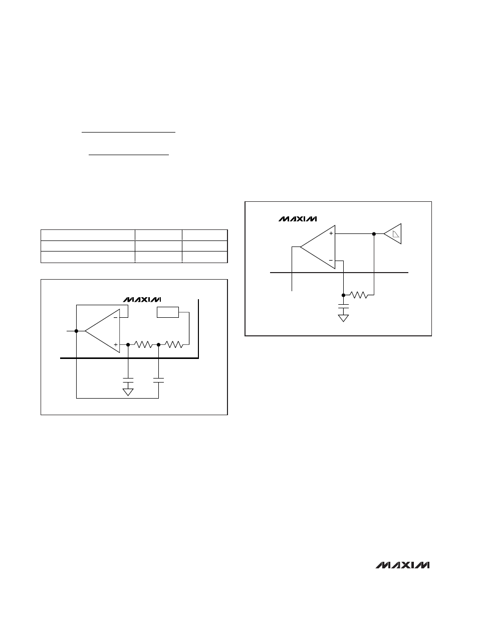
The suggested data-slicer configuration uses a resistor
(R1) connected between DSN and DSP with a capaci-
tor (C4) from DSN to GND (Figure 3). This configuration
averages the analog output of the filter and sets the
threshold to approximately 50% of that amplitude. With
this configuration, the threshold automatically adjusts
as the analog signal varies, minimizing the possibility
for errors in the digital data. The values of R1 and C4
affect how fast the threshold tracks to the analog ampli-
tude. Be sure to keep the corner frequency of the RC
circuit much lower than the lowest expected data rate.
Note that a long string of zeros or ones can cause the
threshold to drift. This configuration works best if a
coding scheme (e.g., Manchester coding, which has an
equal number of zeros and ones) is used.
Peak Detector
The peak-detector output (PDOUT), in conjunction with
an external RC filter, creates a DC output voltage equal
to the peak value of the data signal. The resistor pro-
vides a path for the capacitor to discharge, allowing the
peak detector to dynamically follow peak changes of
the data-filter output voltage. The peak detector can be
used for at least two functions. First, it can serve as an
RSSI for ASK modulation. Second, it can be used for
faster data-slicer response by adding it to the threshold
pin (DSN) on the data-slicer comparator (Figure 4). The
two capacitors in this circuit should be equal, and the
peak detector resistor should be approximately 10
C
k
kHz
pF
C
5
1 000
1 414 100
3 14 6
375
6
=
(
)(
)(
)(
)
=
=
.
.
.
Ω
1
1 414
4 100
3 14 6
186
.
.
( )(
)(
)(
)
=
k
kHz
pF
Ω
300MHz to 450MHz ASK Receiver
with Internal IF Filter
10
______________________________________________________________________________________
FILTER TYPE
a
b
Butterworth (Q = 0.707)
1.414
1.000
Bessel (Q = 0.577)
1.3617
0.618
Table 1. Coefficients to Calculate C5
and C6
16
DSP
C6
C5
R
DF2
100k
Ω
R
DF1
100k
Ω
RSSI
14
OPP
15
DFFB
MAX7036
Figure 2. Sallen-Key Lowpass Data Filter
20
C4
R1
17
DSN
16
DSP
MAX7036
DATA OUT
DATA
SLICER
DATA
FILTER
Figure 3. Generating Data-Slicer Threshold