Electrical characteristics (continued) – Rainbow Electronics MAX8720 User Manual
Page 3
MAX8720
Dynamically Adjustable 6-Bit VID
Step-Down Controller
_______________________________________________________________________________________
3
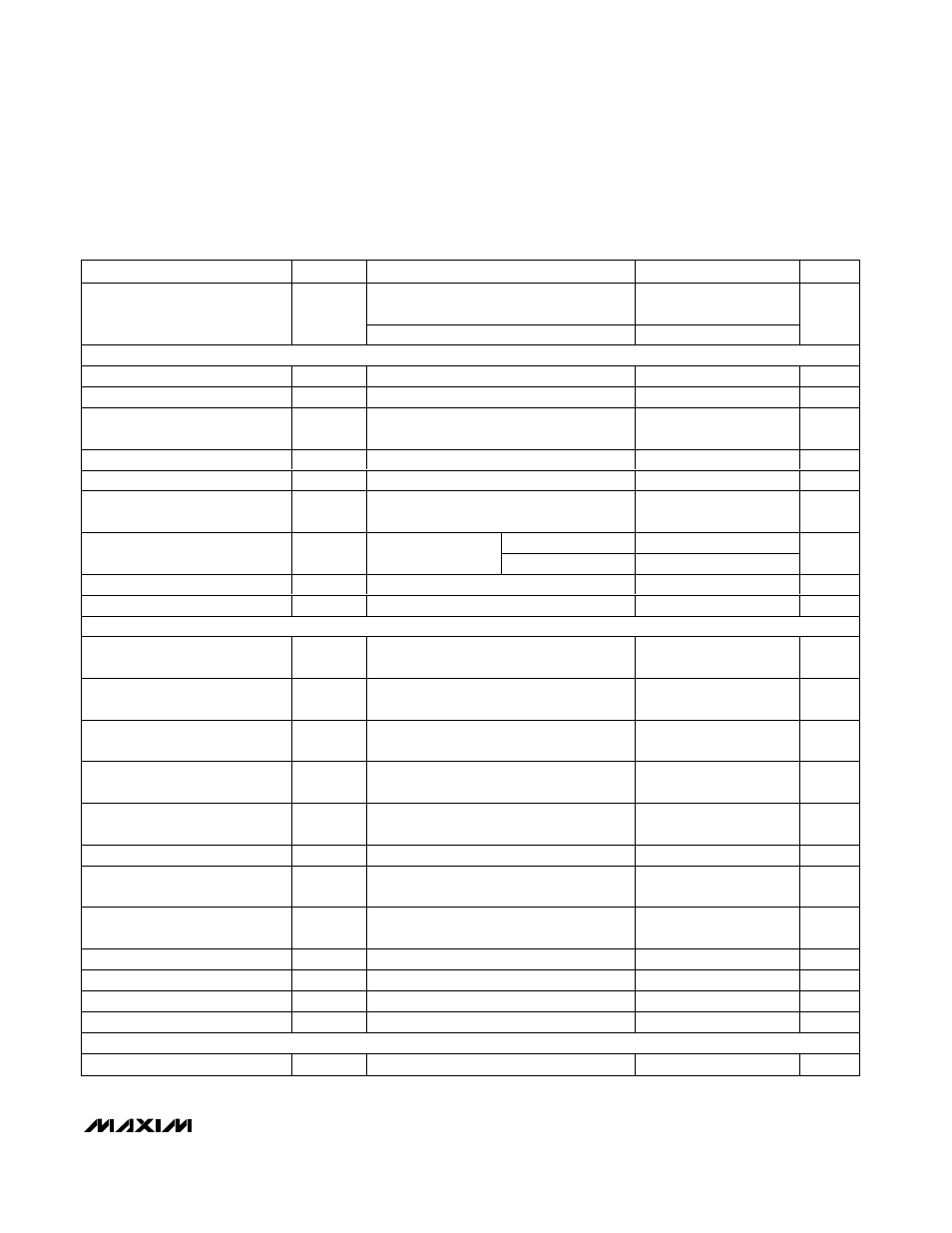
ELECTRICAL CHARACTERISTICS (continued)
(Circuit of Figure 1, V+ = 15V, SHDN = SKIP = V
DD
= V
CC
= +5V, V
OUT
= 1.25V, T
A
= 0°C to +85°C, unless otherwise noted. Typical
values are at T
A
= +25°C.)
PARAMETER
SYMBOL
CONDITIONS
MIN
TYP
MAX
UNITS
TON = V
CC
, open, or REF (200kHz, 300kHz,
or 550kHz)
400
500
Minimum Off-Time (Note 2)
t
OFF(MIN)
TON = GND (1000kHz)
300
375
ns
BIAS AND REFERENCE
Quiescent Supply Current (V
CC
)
I
CC
FB forced above their regulation points
700
1200
µA
Quiescent Supply Current (V
DD
)
I
DD
FB forced above their regulation points
<1
5
µA
Quiescent Battery Supply
Current (V+)
I
+
25
40
µA
Shutdown Supply Current (V
CC
)
I
CC
SHDN = GND
10
25
µA
Shutdown Supply Current (V
DD
)
I
DD
SHDN = GND
<1
5
µA
Shutdown Battery Supply
Current (V+)
I
+
SHDN = GND, V
CC
= V
DD
= 0V or 5V
<1
5
µA
T
A
= + 25
°C to + 85°C 1.985
2.00
2.015
Reference Voltage
V
REF
V
CC
= 4.5V to 5.5V,
I
REF
= 0
T
A
= 0
°C to +85°C
1.98
2.00
2.02
V
Reference Load Regulation
∆V
REF
I
REF
= 0 to 50µA
0.01
V
REF Sink Current
REF in regulation
10
µA
FAULT DETECTION
V
CC
Undervoltage-Lockout
Threshold
Rising edge, hysteresis = 20mV, PWM
disabled below this level
4.1
4.4
V
Output Overvoltage Trip
Threshold
2.20
2.25
2.30
V
Output Overvoltage Fault-
Propagation Delay
t
OVP
FB forced 2% above regulation
10
µs
Output Undervoltage-Protection
Trip Threshold
With respect to unloaded output voltage
65
70
75
%
Output Undervoltage Fault-
Propagation Delay
t
UVP
FB forced 2% below trip threshold
10
µs
PGOOD Transition Blanking Time
After X = Y, clock speed set by R
TIME
8
clk
PGOOD Lower Trip Threshold
Measured at FB with respect to unloaded
output voltage, hysteresis = 1%
-17
-15
-13
%
PGOOD Upper Trip Threshold
Measured at FB with respect to unloaded
output voltage, hysteresis = 1%
+13
+15
+17
%
PGOOD Propagation Delay
t
PGOOD
Falling edge, 50mV overdrive
10
µs
PGOOD Output Low Voltage
I
SINK
= 4mA
0.4
V
PGOOD Leakage Current
I
PGOOD
High state, PGOOD forced to 5.5V
1
µA
Thermal-Shutdown Threshold
T
SHDN
Hysteresis = 10
°C
+150
°C
CURRENT LIMIT
ILIM Adjustment Range
0.5
V
REF
V