Absolute maximum ratings, Electrical characteristics – Rainbow Electronics MAX8720 User Manual
Page 2
MAX8720
Dynamically Adjustable 6-Bit VID
Step-Down Controller
2
_______________________________________________________________________________________
ABSOLUTE MAXIMUM RATINGS
(Note 1)
Stresses beyond those listed under “Absolute Maximum Ratings” may cause permanent damage to the device. These are stress ratings only, and functional
operation of the device at these or any other conditions beyond those indicated in the operational sections of the specifications is not implied. Exposure to
absolute maximum rating conditions for extended periods may affect device reliability.
V
CC
to AGND............................................................-0.3V to +6V
V
DD
to PGND............................................................-0.3V to +6V
AGND to PGND .....................................................-0.3V to +0.3V
V+ to PGND............................................................-0.3V to +30V
SHDN to AGND ......................................................-0.3V to +16V
D0–D5, PGOOD, SUS, SKIP to AGND .....................-0.3V to +6V
FB, FBS, GNDS to AGND ...........................-0.3V to (V
CC
+ 0.3V)
CC, ILIM, REF, TIME to AGND ...................-0.3V to (V
CC
+ 0.3V)
S0, S1, TON to AGND ................................-0.3V to (V
CC
+ 0.3V)
BST to PGND..........................................................-0.3V to +36V
LX to BST..................................................................-6V to +0.3V
DH to LX .....................................................-0.3V to (BST + 0.3V)
DL to PGND................................................-0.3V to (V
DD
+ 0.3V)
REF Short Circuit to AGND.........................................Continuous
Continuous Power Dissipation (T
A
= +70°C)
28-Pin QSOP (derate 10.8mW/°C above +70°C)........860mW
36-Pin TQFN (derate 26.3mW/°C above +70°C) .....2105mW
Operating Temperature
Extended Temperature Range .......................-40°C to +85°C
Junction Temperature ......................................................+150°C
Storage Temperature Range .............................-65°C to +165°C
Lead Temperature (soldering, 10s) .................................+300°C
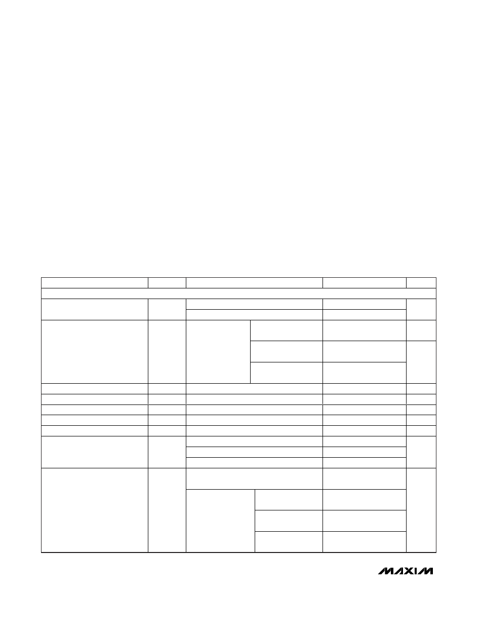
ELECTRICAL CHARACTERISTICS
(Circuit of Figure 1, V+ = 15V, SHDN = SKIP = V
DD
= V
CC
= +5V, V
OUT
= 1.25V, T
A
= 0°C to +85°C, unless otherwise noted. Typical
values are at T
A
= +25°C.)
PARAMETER
SYMBOL
CONDITIONS
MIN
TYP
MAX
UNITS
PWM CONTROLLER
Battery voltage, V+
2
28
Input Voltage Range
V
CC
, V
DD
4.5
5.5
V
DAC codes from
0.9V to 1.85V
-1
+1
%
DAC codes from
0.45V to 0.875V
-10
+10
DC Output Voltage Accuracy
V+ = 4.5V to 28V,
includes load
regulation error
DAC codes from
0.275V to 0.425V
-18
+18
mV
Line Regulation Error
V
CC
= 4.5V to 5.5V, V+ = 4.5V to 28V
5
mV
Remote-Sense Voltage Error
FB to FBS or AGND to GNDS = 0 to 25mV
3
mV
FBS Input Bias Current
FB, FBS
-0.2
+0.2
µA
GNDS Input Bias Current
GNDS
-1
+1
µA
FB Input Resistance
115
180
265
k
Ω
150kHz, R
TIME
= 120k
Ω
-8
+8
818kHz, R
TIME
= 22k
Ω
-12
+12
TIME Frequency Accuracy
38kHz, R
TIME
= 470k
Ω
-12
+12
%
V+ = 5V, FB = 1.25V, TON = GND
(1000kHz)
230
260
290
TON = REF
(550kHz)
165
190
215
TON = open
(300kHz)
320
355
390
On-Time (Note 2)
t
ON
V+ = 12V,
FB = 1.25V
TON = V
CC
(200kHz)
465
515
565
ns
Note 1: For the MAX8720EEI, AGND and PGND refer to a single pin designated GND.