Max8720, Shdn, Soft-startup and soft-shutdown – Rainbow Electronics MAX8720 User Manual
Page 18: Nominal output voltage setting
MAX8720
Soft-Startup and Soft-Shutdown (
SHDN
)
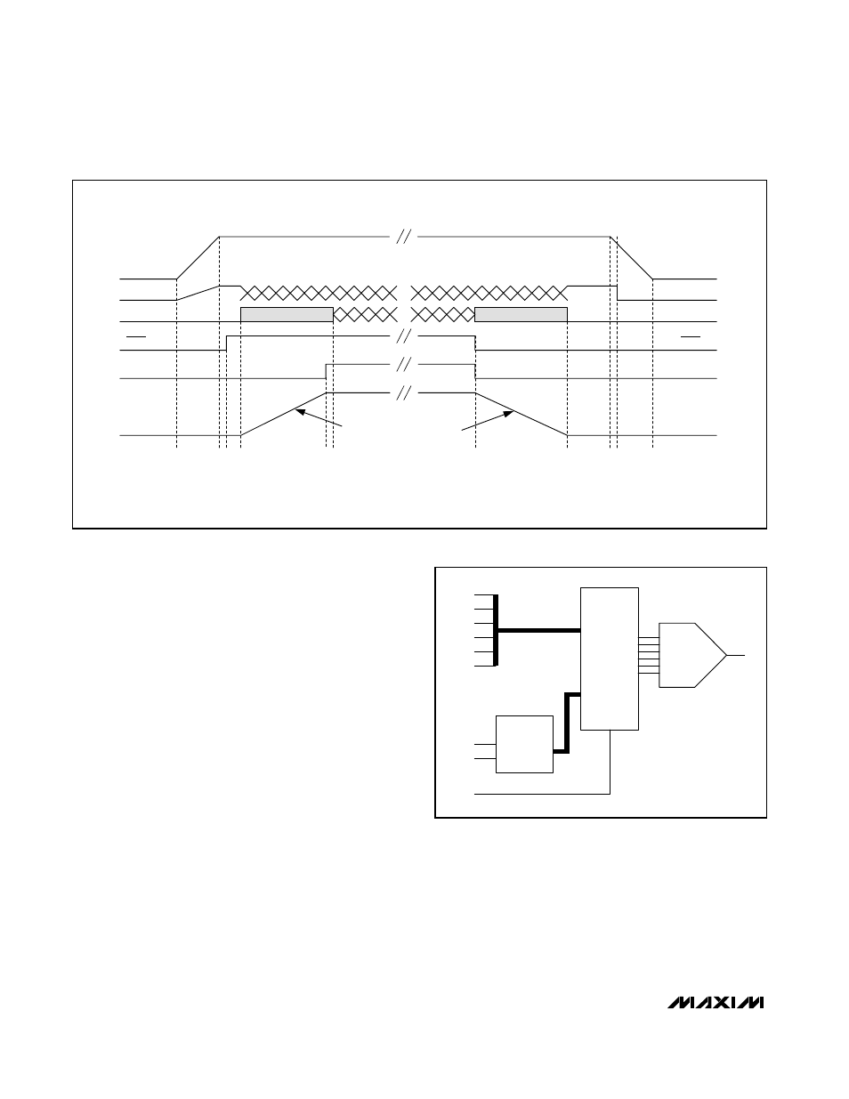
When SHDN goes low, the MAX8720 enters low-power
shutdown mode. PGOOD goes low immediately. The
output voltage ramps down to 0V in 25mV steps at
1/4th the clock rate set by R
TIME
. The slow rampdown
of the output voltage results in smaller negative induc-
tor currents, eliminating negative voltages on the out-
put. When the DAC reaches the 0V setting, DL goes
high, DH goes low, the reference is turned off, and the
supply current drops to approximately 10µA.
When SHDN goes high, the reference powers up, and
after the reference UVLO is passed, the DAC target is
evaluated and switching begins. The slew-rate controller
ramps up from 0V in 25mV steps at 1/4th the clock rate
set by R
TIME
to the currently selected code value
(based on SUS). Full output current is available immedi-
ately. PGOOD goes high after the slew-rate controller
has terminated and the output voltage is in regulation.
Nominal Output Voltage Setting
The MAX8720 uses a multiplexer that selects from two
different inputs (Figure 7)—the VID DAC inputs or the
suspend-mode S0, S1 inputs. On startup, the MAX8720
slews the target voltage from ground to either the
decoded D0–D5 (SUS = low) voltage or the S0, S1 volt-
age (SUS = high).
DAC Inputs (D0–D5)
The digital-to-analog converter (DAC) programs the out-
put voltage. It typically receives a preset digital code
from the CPU pins, which are either hardwired to GND
or left open-circuit. They can also be driven by digital
logic, general-purpose I/O, or an external mux. Do not
leave D0–D5 floating—use 1M
Ω or less pullup resistors
if the inputs may float. D0–D5 can be changed while the
Dynamically Adjustable 6-Bit VID
Step-Down Controller
18
______________________________________________________________________________________
PGOOD
SOFT-STARTUP AND SHUTDOWN
1/4TH SLEW RATE SET BY R
TIME
8x R
TIME
CLOCKS
V
CPU
V
CC
MODE
PGOOD
V
CPU
V
CC
PWM
DL
DL
V
CC(UVLO)
FORCED-PWM MODE
FORCED-PWM MODE
SHDN
SHDN
Figure 6. Soft-Startup and Soft-Shutdown
6-BIT
CODE
0
D5
D0
D1
D2
D3
D4
S1
S0
S0/S1
DECODER
OUT
IN
SUS MUX
1
SEL
SUS
6-BIT
CODE
OUT
DAC
Figure 7. Internal Multiplexers Functional Diagram