Pin description – Rainbow Electronics MAX8720 User Manual
Page 10
MAX8720
Dynamically Adjustable 6-Bit VID
Step-Down Controller
10
______________________________________________________________________________________
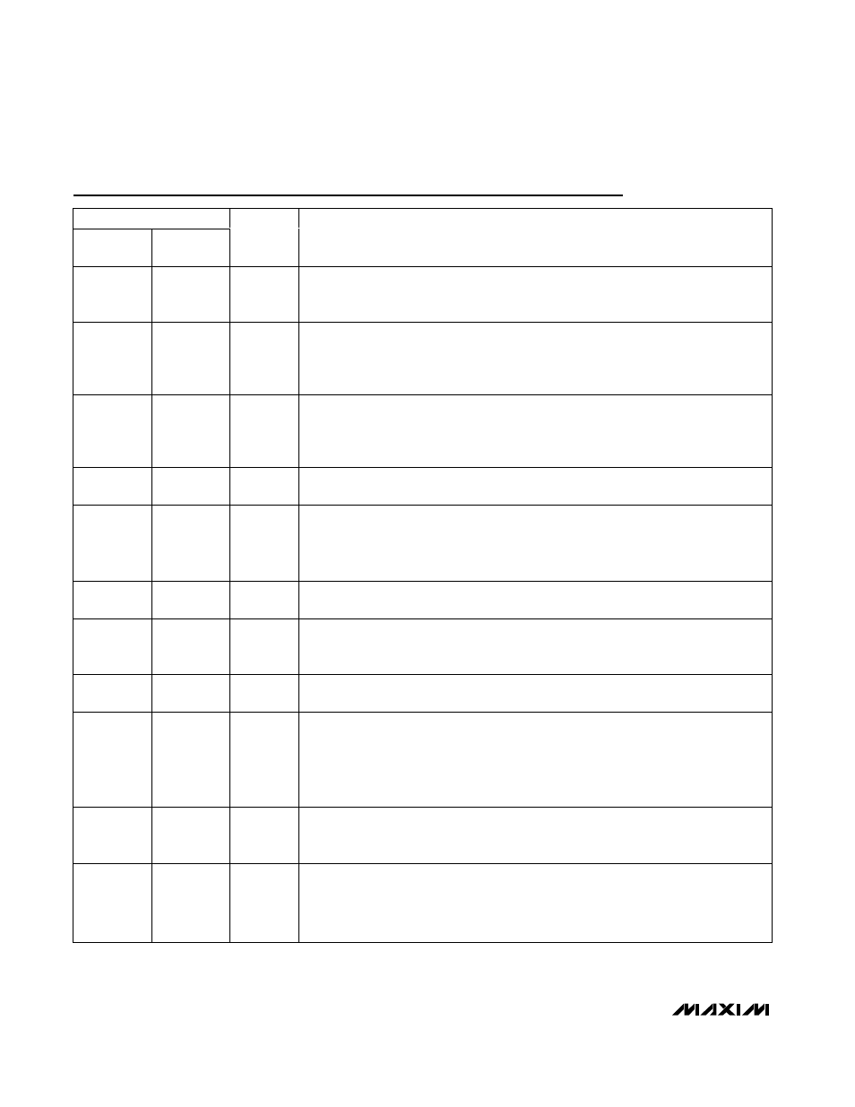
Pin Description
PIN
28 QSOP
36 THIN
QFN
NAME
FUNCTION
1
33
V+
Battery Voltage-Sense Connection. Connect V+ to input power source. V+ is used only
for PWM one-shot timing. DH on-time is inversely proportional to input voltage over a 2V
to 28V range.
2
34
SHDN
Shutdown Control Input. Connect SHDN to V
CC
for normal operation. Connect SHDN to
GND to put the controller into its shutdown state. Forcing SHDN to 12V to 15V disables
both the overvoltage-protection and undervoltage-protection circuits and clears the fault
latch. Do not connect SHDN to >15V.
3
35
TIME
Slew-Rate Adjustment Pin. Connect a resistor from TIME to GND to set the internal slew-
rate clock. A 470k
Ω to 22kΩ resistor sets the clock from 38kHz to 818kHz, f
SLEW
=
150kHz x 120k
Ω / R
TIME
. To reduce inrush current, f
SLEW
= 150kHz x 120k
Ω / 4 x R
TIME
during power-up and power-down transient.
4
1
FB
Fast Feedback Input. Connect FB to the junction of the external inductor and output-
capacitor node (Figure 1).
5
2
FBS
Feed b ack Rem ote- S ense Inp ut. For nonvol tag e- p osi ti oned ci r cui ts, connect FBS to V
OU T
d i r ectl y at the l oad . FBS i nter nal l y connects to the i nteg r ator that fi ne tunes the D C outp ut
vol tag e. For vol tag e- p osi ti oned ci r cui ts, connect FBS d i r ectl y to FB near the IC to d i sab l e the
FBS r em ote- sense i nteg r ator am p l i fi er . To d i sab l e al l thr ee i nteg r ator am p l i fi er s, connect FBS
to V
C C
.
6
3
CC
Integ r ator C ap aci tor C onnecti on. C onnect a 47p F to 1000p F ( 47p F typ ) cap aci tor fr om C C to
AGN D to set the i nteg r ati on ti m e constant. C C can b e l eft op en i f FBS i s connected to V
C C
.
7, 8
4, 5
S0, S1
S usp end - M od e V ol tag e- S el ect Inp ut. S 0 and S 1 ar e four - l evel d i g i tal i np uts that sel ect the
susp end - m od e V ID cod e for the susp end - m od e m ul ti p l exer i np uts. If S U S i s hi g h, the
susp end - m od e V ID cod e i s d el i ver ed to the D AC .
9
7
V
CC
Anal og S up p l y Inp ut. C onnect to the system sup p l y vol tag e ( + 4.5V to + 5.5V ) thr oug h a ser i es
10
Ω r esi stor . Byp ass V
C C
to anal og g r ound w i th a 1µF or g r eater cer am i c cap aci tor .
10
8
TON
On-Time Selection Control Input. This is a four-level input that sets the K-factor to
determine DH on-time. Connect TON to the following pins for the indicated operation:
GND = 1000kHz
REF = 550kHz
Open = 300kHz
V
CC
= 200kHz
11
9
REF
2.0V Reference Voltage Output. Bypass REF to analog ground with a 0.22µF or greater
ceramic capacitor. The reference can source up to 50µA for external loads. Loading REF
degrades output voltage accuracy according to the REF load regulation error.
12
10
ILIM
Current-Limit Adjustment. The PGND–LX current-limit threshold defaults to 100mV if ILIM
is connected to V
CC
. In adjustable mode, the current-limit threshold voltage is 1/10th the
voltage seen at ILIM over a 0.5V to 3.0V range. The logic threshold for switchover to the
100mV default value is approximately V
CC
- 1V. Connect ILIM to REF for a fixed 200mV
threshold.