Max8720, Detailed description, 5v bias supply (v – Rainbow Electronics MAX8720 User Manual
Page 12: And v, Reference (ref)
MAX8720
Detailed Description
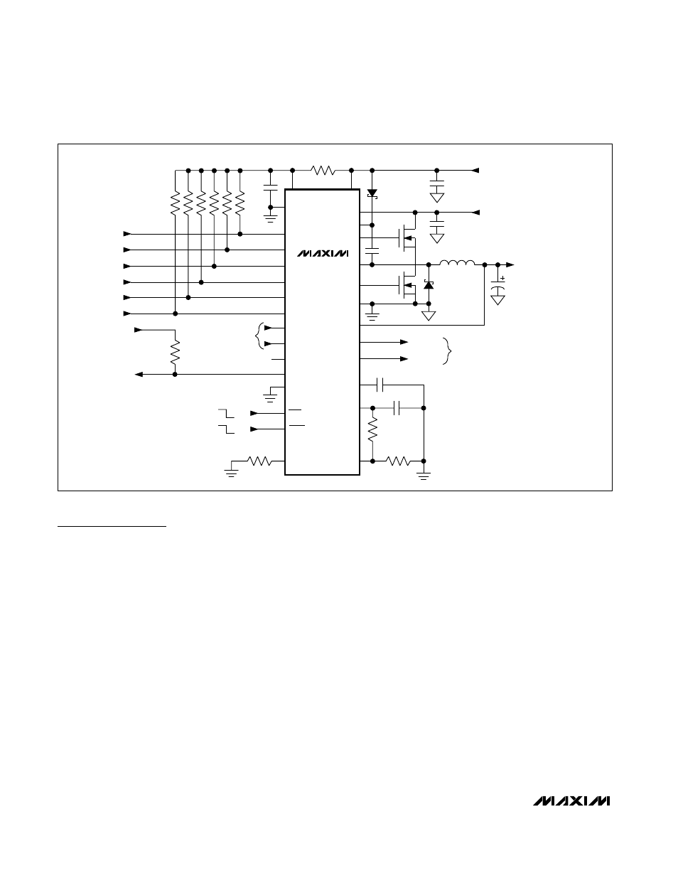
The MAX8720 is a constant-on-time, quick-PWM con-
troller with 6-bit VID inputs to dynamically set the output
voltage from 0.275V to 1.85V. The MAX8720 standard
application circuit (Figure 1) generates a low-voltage
1.25V/15A output typical of low-power CPU and GPU
core supplies in a notebook computer. The input sup-
ply range is 7V to 24V. See Table 1 for component
selections and Table 2 for component manufacturers.
5V Bias Supply (V
CC
and V
DD
)
The MAX8720 requires an external 5V bias supply in
addition to the battery. Typically, this 5V bias supply is
the notebook’s 95%-efficient, 5V system supply.
Keeping the bias supply external to the IC improves
efficiency and eliminates the cost associated with the
5V linear regulator that would otherwise be needed to
supply the PWM circuit and gate drivers. If stand-alone
capability is needed, the 5V supply can be generated
with an external linear regulator.
The 5V bias supply must provide V
CC
(PWM controller)
and V
DD
(gate-drive power), so the maximum current
drawn is:
I
BIAS
= I
CC
+ f
SW
(Q
G(LOW)
+ Q
G(HIGH)
)
= 4mA to 40mA (typ)
where I
CC
is 800µA (typ), f
SW
is the switching frequency,
and Q
G(LOW)
and Q
G(HIGH)
are the MOSFET data
sheet’s total gate-charge specification limits at V
GS
= 5V.
V+ and V
DD
can be connected together if the input power
source is a fixed 4.5V to 5.5V supply. If the 5V bias supply
is powered up prior to the battery supply, the enable sig-
nal (SHDN going from low to high) must be delayed until
the battery voltage is present to ensure startup.
Reference (REF)
The 2V reference is accurate to ±0.75% over tempera-
ture and load, making REF useful as a precision system
reference. Bypass REF to GND with a 0.22µF or greater
ceramic capacitor. The reference sources up to 100µA
and sinks 10µA to support external loads. Loading the
reference reduces the output voltages slightly, because
of the reference load regulation error.
Dynamically Adjustable 6-Bit VID
Step-Down Controller
12
______________________________________________________________________________________
MAX8720
PGOOD
OPEN (300kHz)
PGOOD
VID0
VID1
VID2
VID3
VID4
VID5
SUS
D
BST
V
CPU_SENSE
V
GND_SENSE
D
L
AGND*
OUTPUT
(V
OUT
)
C
OUT
(3) 470
µF
L1
0.8
µH
INPUT (V
IN
)
7V TO 28V
BST
C2
1
µF
V+
DH
LX
DL
*PGND
FB
V
CC
V
DD
SHDN
+5V BIAS
C1
1
µF
C
BST
0.1
µF
C
REF
0.22
µF
C
IN
(2) 10
µF
FBS
CONNECT TO REMOTE-
SENSE POINTS
*FOR THE MAX8720EEI, AGND AND PGND
REFER TO A SINGLE PIN DESIGNATED GND
GNDS
CC
REF
ILIM
SKIP
SKIP
TIME
D0
D1
D2
N
H
N
L
D3
D4
D5
S0
S1
R1
10
Ω
R8
100k
Ω
R2 TO R7
(6) 100k
Ω
R
ILIM1
100k
Ω
R
ILIM2
33.2k
Ω
C
CC
47pF
+5V BIAS
TON
R
TIME
100k
Ω
4-LEVEL
SUSPEND
INPUTS
OFF
PWM
ON
Figure 1. MAX8720 Standard Application Circuit