Max8720 – Rainbow Electronics MAX8720 User Manual
Page 14
MAX8720
On-times translate only roughly to switching frequen-
cies. The on-times guaranteed in the Electrical
Characteristics table are influenced by switching delays
in the external high-side MOSFET. Resistive losses,
including the inductor, both MOSFETs, output-capacitor
ESR, and PC board copper losses in the output and
ground tend to raise the switching frequency at higher
output currents. Also, the dead-time effect increases the
effective on-time, reducing the switching frequency. It
occurs only in PWM mode (SKIP = high) and during
Dynamically Adjustable 6-Bit VID
Step-Down Controller
14
______________________________________________________________________________________
REF
-15%
FROM
D/A
REF
REF
SKIP
SUS
S0, S1
D0–D5
TIME
10k
Ω
ERROR
AMP
TOFF
TON
REF
+15%
FB
R-2R
D/A CONVERTER
CHIP SUPPLY
G
m
G
m
G
m
GNDS
CC
FBS
PGOOD
ON-TIME
COMPUTE
TON
ONE-SHOT
ONE-SHOT
TRIG
V
BATT
2V TO 28V
TRIG
Q
Q
S
R
2V
REF
REF
FB
PGND
+5V
V
OUT
DL
V
CC
V
DD
LX
ZERO CROSSING
CURRENT
LIMIT
DH
BST
ILIM
REF
+5V
+5V
Q
OVP/UVP
DETECT
SHDN
TON
V+
70k
Ω
Σ
MAX8720
S
R
Q
MUX AND SLEW CONTROL
9
1
AGND
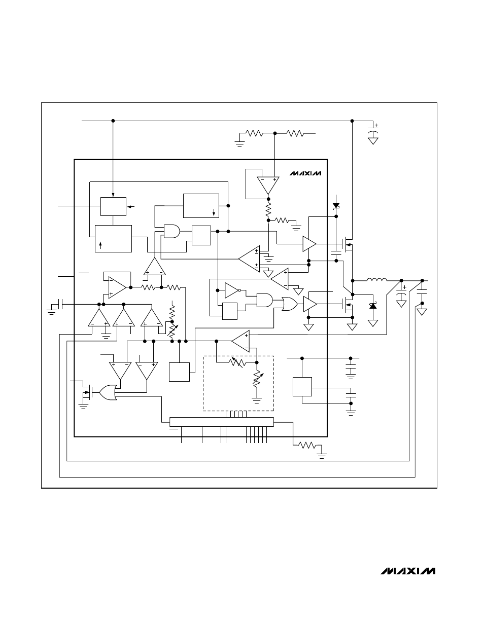
Figure 2. MAX8720 Block Diagram