Table 4. output voltage vs. dac codes – Rainbow Electronics MAX8720 User Manual
Page 19
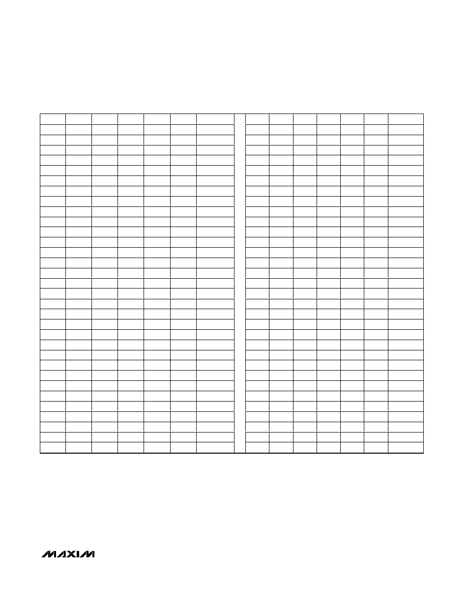
SMPS is active, initiating a transition to a new output
voltage level. If this mode of DAC control is used, con-
nect SUS low. Change D0–D5 together, avoiding
greater than 50ns skew between bits. Otherwise, incor-
rect DAC readings may cause a partial transition to the
wrong voltage level, followed by the intended transition
to the correct voltage level, lengthening the overall tran-
sition time. The available DAC codes and resulting out-
put voltages are shown in Table 4.
Suspend Mode (S0, S1, SUS)
When the CPU enters low-power suspend mode, the
processor sets the regulator to a lower output voltage
to reduce power consumption. The MAX8720 includes
a suspend-mode input (S0, S1) and a digital SUS con-
trol input. The suspend voltage is programmed using
the 4-level S0, S1 inputs (Table 5). The suspend volt-
age adjustment range is from 0.275V to 0.650V.
MAX8720
Dynamically Adjustable 6-Bit VID
Step-Down Controller
______________________________________________________________________________________
19
D5
D4
D3
D2
D1
D0
V
OUT
D5
D4
D3
D2
D1
D0
V
OUT
0
0
0
0
0
0
1.850
1
0
0
0
0
0
1.050
0
0
0
0
0
1
1.825
1
0
0
0
0
1
1.025
0
0
0
0
1
0
1.800
1
0
0
0
1
0
1.000
0
0
0
0
1
1
1.775
1
0
0
0
1
1
0.975
0
0
0
1
0
0
1.750
1
0
0
1
0
0
0.950
0
0
0
1
0
1
1.725
1
0
0
1
0
1
0.925
0
0
0
1
1
0
1.700
1
0
0
1
1
0
0.900
0
0
0
1
1
1
1.675
1
0
0
1
1
1
0.875
0
0
1
0
0
0
1.650
1
0
1
0
0
0
0.850
0
0
1
0
0
1
1.625
1
0
1
0
0
1
0.825
0
0
1
0
1
0
1.600
1
0
1
0
1
0
0.800
0
0
1
0
1
1
1.575
1
0
1
0
1
1
0.775
0
0
1
1
0
0
1.550
1
0
1
1
0
0
0.750
0
0
1
1
0
1
1.525
1
0
1
1
0
1
0.725
0
0
1
1
1
0
1.500
1
0
1
1
1
0
0.700
0
0
1
1
1
1
1.475
1
0
1
1
1
1
0.675
0
1
0
0
0
0
1.450
1
1
0
0
0
0
0.650
0
1
0
0
0
1
1.425
1
1
0
0
0
1
0.625
0
1
0
0
1
0
1.400
1
1
0
0
1
0
0.600
0
1
0
0
1
1
1.375
1
1
0
0
1
1
0.575
0
1
0
1
0
0
1.350
1
1
0
1
0
0
0.550
0
1
0
1
0
1
1.325
1
1
0
1
0
1
0.525
0
1
0
1
1
0
1.300
1
1
0
1
1
0
0.500
0
1
0
1
1
1
1.275
1
1
0
1
1
1
0.475
0
1
1
0
0
0
1.250
1
1
1
0
0
0
0.450
0
1
1
0
0
1
1.225
1
1
1
0
0
1
0.425
0
1
1
0
1
0
1.200
1
1
1
0
1
0
0.400
0
1
1
0
1
1
1.175
1
1
1
0
1
1
0.375
0
1
1
1
0
0
1.150
1
1
1
1
0
0
0.350
0
1
1
1
0
1
1.125
1
1
1
1
0
1
0.325
0
1
1
1
1
0
1.100
1
1
1
1
1
0
0.300
0
1
1
1
1
1
1.075
1
1
1
1
1
1
0.275
Table 4. Output Voltage vs. DAC Codes