Max8720, Table 5. suspend-mode dac codes – Rainbow Electronics MAX8720 User Manual
Page 20
MAX8720
When the CPU suspends operation (SUS = high), the
controller overrides the 6-bit VID DAC code set by
D0–D5, and slews the output voltage to the target volt-
age set by the S0, S1 inputs. During the transition, the
MAX8720 blanks both PGOOD thresholds (PGOOD
forced high impedance) until the slew-rate controller
reaches the suspend-mode voltage, plus 8 extra R
TIME
clocks. After this blanking time expires, the MAX8720
automatically switches to a pulse-skipping control
scheme regardless of SKIP.
Output-Voltage-Transition Timing
The MAX8720 is designed to perform output-voltage
transitions in a controlled manner, automatically mini-
mizing input surge currents. This feature allows the cir-
cuit designer to achieve nearly ideal transitions,
guaranteeing just-in-time arrival at the new output-volt-
age level with the lowest possible peak currents for a
given output capacitance. This makes the IC ideal for
CPUs and GPUs that operate at different voltages.
At the beginning of an output-voltage transition (VID
change or SUS level change), the MAX8720 enters
forced-PWM mode and blanks the PGOOD output
(forced high impedance). PGOOD remains blanked
during the transition and is re-enabled when the slew-
rate controller has set the internal DAC to the final value
and 8 additional slew-rate clock periods have passed.
The slew-rate clock frequency (set by resistor R
TIME
)
must be set fast enough to ensure that the longest
required transition is completed within the allowed tran-
sition time.
The output-voltage transition is performed in 25mV
steps, preceded by a delay and followed by one addi-
tional clock period. The total time for a transition
depends on R
TIME
, the voltage difference, and the
accuracy of the MAX8720’s slew-rate clock, and is not
dependent on the total output capacitance. The greater
the output capacitance, the higher the surge current
required for the transition. The MAX8720 automatically
controls the current to the minimum level required to
complete the transition in the calculated time, as long
as the surge current is less than the current limit set by
ILIM. The transition time is given by:
where f
SLEW
= 150kHz x 120k
Ω / R
TIME
, V
OLD
is the
original DAC setting, V
NEW
is the new DAC setting, and
t
DELAY
ranges from zero to a maximum of 2 / f
SLEW
.
See Time Frequency Accuracy in the Electrical Char-
acteristics table for f
SLEW
accuracy. The practical
range of R
TIME
is 22k
Ω to 470kΩ, corresponding to
1.22µs to 26µs per 25mV step. Although the DAC takes
discrete 25mV steps, the output filter makes the transi-
tions relatively smooth. The average inductor current
required to make an output-voltage transition is:
Suspend Transition
(Forced-PWM Operation Selected)
When the MAX8720 enters suspend mode while config-
ured for forced-PWM operation (SKIP pulled high), the
controller ramps the output voltage down to the S0, S1
programmed voltage at the slew rate determined by
R
TIME
. The controller blanks PGOOD (forced high
impedance) until the transition is completed plus 8 extra
R
TIME
clocks—the internal target voltage equals the
selected S0, S1 DAC voltage. After this blanking time
expires, the controller enters pulse-skipping operation.
When exiting suspend mode (SUS pulled low), the
MAX8720 immediately enters forced-PWM mode and
ramps the output up at the slew rate set by R
TIME
. The
controller blanks PGOOD (forced high impedance) until
the transition is completed plus 8 extra R
TIME
clocks—
the internal target voltage equals the selected D0–D5
DAC voltage.
I
C
mV
f
L AVE
OUT
SLEW
(
)
=
Ч
Ч
25
t
V
V
mV f
t
TRANS
OLD
NEW
SLEW
DELAY
=
−
×
+
|
|
25
Dynamically Adjustable 6-Bit VID
Step-Down Controller
20
______________________________________________________________________________________
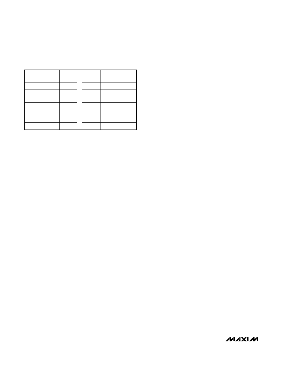
S1
S0
V
OUT
S1
S0
V
OUT
GND
GND
0.650
OPEN
GND
0.450
GND
REF
0.625
OPEN
REF
0.425
GND
OPEN
0.600
OPEN
OPEN
0.400
GND
V
CC
0.575
OPEN
V
CC
0.375
REF
GND
0.550
V
CC
GND
0.350
REF
REF
0.525
V
CC
REF
0.325
REF
OPEN
0.500
V
CC
OPEN
0.300
REF
V
CC
0.475
V
CC
V
CC
0.275
Table 5. Suspend-Mode DAC Codes