T5744 – Rainbow Electronics T5744 User Manual
Page 4
4
T5744
4521A–RKE–02/02
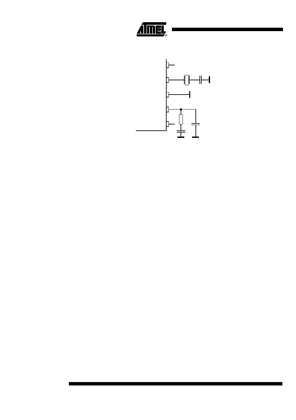
Figure 4. PLL Peripherals
The passive loop filter connected to Pin LF is designed for a loop bandwidth of BLoop =
100 kHz. This value for BLoop exhibits the best possible noise performance of the LO.
Figure 4 shows the appropriate loop filter components to achieve the desired loop
bandwidth
f
LO
is determined by the RF input frequency f
RF
and the IF frequency f
IF
using the follow-
ing formula:
f
LO
= f
RF
- f
IF
To determine f
LO
, the construction of the IF filter must be considered at this point. The
nominal IF frequency is f
IF
= 1 MHz. To achieve a good accuracy of the filter’s corner fre-
quencies, the filter is tuned by the crystal frequency f
XTO
. This means that there is a
fixed relation between f
IF
and f
LO
that depends on the logic level at pin mode. This is
described by the following formulas:
MODE = 0 USA f
IF
= f
LO
/314
MODE = 1 Europe f
IF
= f
LO
/432.92
The relation is designed to achieve the nominal IF frequency of f
IF
= 1 MHz for most
applications. For applications where f
RF
= 315 MHz, MODE must be set to ’0’. In the
case of f
RF
= 433.92 MHz, MODE must be set to ’1’. For other RF frequencies, f
IF
is
not equal to 1 MHz. f
IF
is then dependent on the logical level at Pin MODE and on f
RF
.
Table 1 summarizes the different conditions.
The RF input either from an antenna or from a generator must be transformed to the RF
input Pin LNA_IN. The input impedance of that pin is provided in the electrical parame-
ters. The parasitic board inductances and capacitances also influence the input
matching. The RF receiver T5744 exhibits its highest sensitivity at the best signal-to-
noise ratio in the LNA. Hence, noise matching is the best choice for designing the trans-
formation network.
A good practice when designing the network, is to start with power matching. From that
starting point, the values of the components can be varied to some extent to achieve the
best sensitivity.
If a SAW is implemented into the input network a mirror frequency suppression of
∆
P
Ref
= 40 dB can be achieved. There are SAWs available that exhibit a notch at
∆
f = 2 MHz. These SAWs work best for an intermediate frequency of IF = 1 MHz. The
selectivity of the receiver is also improved by using a SAW. In typical automotive appli-
cations, a SAW is used.
DVCC
XTO
LF
LFVCC
LFGND
V
C
C10
R1
C9
S
L
V
S
R1 = 820
Ω
C9 = 4.7 nF
C10 = 1 nF