T5744, Electrical characteristics (continued) – Rainbow Electronics T5744 User Manual
Page 13
13
T5744
4521A–RKE–02/02
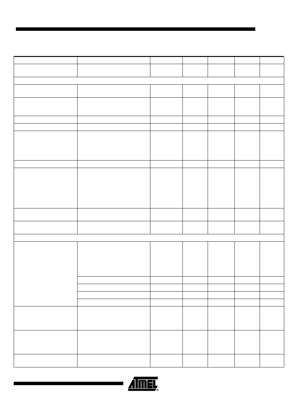
Maximum input level
Input matched according to
Figure 6, BER
≤
10
-3
P
in_max
-20
dBm
Local Oscillator
Operating frequency range
VCO
f
VCO
299
449
MHz
Phase noise VCO / LO
f
osc
= 432.92 MHz
at 1 MHz
at 10 MHz
L (fm)
-93
-113
-90
-110
dBC/Hz
dBC/Hz
Spurious of the VCO
at ± f
XTO
-55
-47
dBC
VCO gain
K
VCO
190
MHz/V
Loop bandwidth of the PLL
For best LO noise
(design parameter)
R1 = 820
Ω
C9 = 4.7 nF
C10 = 1 nF
B
Loop
100
kHz
Capacitive load at Pin LF
C
LF_tot
10
nF
XTO operating frequency
XTO crystal frequency,
appropriate load capacitance
must be connected to XTAL
f
XTAL
= 6.764375 MHz (EU)
f
XTAL
= 4.90625 MHz (US)
f
XTO
6.764375
-30 ppm
4.90625
-30 ppm
6.764375
4.90625
6.764375
+30 ppm
4.90625
+30 ppm
MHz
MHz
Series resonance resistor of
the crystal
f
XTO
= 6.764 MHz
4.906 MHz
R
S
150
220
Ω
Ω
Static capacitance of the
crystal
C
o
6.5
pF
Analog Signal Processing
Input sensitivity
Input matched according to
Figure 6
ASK (level of carrier)
BER
≤
10
-3
(Manchester),
f
in
= 433.92 MHz/ 315 MHz
T = 25°C, V
S
= 5 V, f
IF
= 1 MHz
P
Ref_ASK
BR_Range0 (1 kBd)
-107
-110
-112
dBm
BR_Range1 (2 kBd)
-105
-108
-110
dBm
BR_Range2 (4kBd)
-103
-106
-108
dBm
BR_Range3 (8 kBd)
-101
-104
-106
dBm
Sensitivity variation for the
full operating range
compared to
T
amb
= 25
°
C, V
S
= 5 V
f
in
= 433.92 MHz/ 315 MHz
f
IF
= 1 MHz
P
ASK
= P
Ref_ASK
+ DP
Ref
∆
P
Ref
+2.5
-1.5
dB
Sensitivity variation for full
operating range including IF
filter compared to
T
amb
= 25°C, V
S
= 5 V
f
in
= 433.92 MHz/ 315 MHz
f
IF
= 0.79 MHz to 1.21 MHz
f
IF
= 0.73 MHz to 1.27 MHz
P
ASK
= P
Ref_ASK
+ DP
Ref
∆
P
Ref
+5.5
+7.5
-1.5
-1.5
dB
dB
S/N ratio to suppress inband
noise signals
SNR
10
12
dB
Electrical Characteristics (continued)
Parameters
Test Conditions
Symbol
Min.
Typ.
Max.
Unit