Ac electrical characteristics (continued) – Rainbow Electronics MAX7057 User Manual
Page 4
MAX7057
300MHz to 450MHz Frequency-Programmable
ASK/FSK Transmitter
4
_______________________________________________________________________________________
AC ELECTRICAL CHARACTERISTICS (continued)
(
Typical Application Circuit, 50Ω system impedance, tuned for 315MHz to 433.92MHz operation, AVDD = DVDD = PAVDD = +2.1V to
+3.6V, fRF = 300MHz to 450MHz, f
CRYSTAL
= 16MHz, T
A
= -40°C to +125°C, unless otherwise noted. Typical values are at AVDD =
DVDD = PAVDD = +2.7V, T
A
= +25°C, unless otherwise noted. All min and max values are 100% tested at T
A
= +125°C, and guaran-
teed by design and characterization over temperature, unless otherwise noted.)
PARAMETER
SYMBOL
CONDITIONS
MIN
TYP
MAX
UNITS
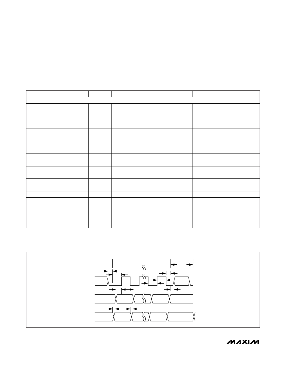
SERIAL INTERFACE (SPI) TIMING CHARACTERISTICS (Figure 1)
Minimum SCLK Low to Falling-
Edge of
CS Setup Time
t
SC
10
ns
Minimum
CS Low to Rising-Edge
of SCLK Setup Time
t
CSS
5
ns
Minimum SCLK Low to Rising-
Edge of
CS Setup Time
t
HCS
20
ns
Minimum SCLK Low After Rising-
Edge of
CS Hold Time
t
HS
5
ns
Minimum Data Valid to SCLK
Rising-Edge Setup Time
t
DS
10
ns
Minimum Data Valid to SCLK
Rising-Edge Hold Time
t
DH
5
ns
Minimum SCLK High Pulse Width
t
CH
40
ns
Minimum SCLK Low Pulse Width
t
CL
40
ns
Minimum
CS High Pulse Width
t
CSH
40
ns
Maximum Transition Time from
Falling-Edge of
CS to Valid GPO
t
CSG
C
L
= 10pF load capacitance from GPO to
DGND
50
ns
Maximum Transition Time from
Falling-Edge of SCLK to Valid
GPO
t
CG
C
L
= 10pF load capacitance from GPO to
DGND
50
ns
Note 1: Supply current and output power are greatly dependent on board layout and PAOUT match.
Note 2: 50% duty cycle at 10kHz ASK data (Manchester coded).
Note 3: Guaranteed by design and characterization, not production tested.
Note 4: Dependent on PCB trace capacitance.
t
SC
t
HCS
t
HS
t
DH
t
CG
t
CSG
t
DS
t
CSH
t
CH
t
CL
t
CSS
CS
SCLK
SDI
GPO
Figure 1. SPI Timing Diagram