Table 3. register configuration, Table 4. control register (address: 0x00) – Rainbow Electronics MAX7057 User Manual
Page 14
MAX7057
300MHz to 450MHz Frequency-Programmable
ASK/FSK Transmitter
14
______________________________________________________________________________________
BIT
NAME
FUNCTION
4-0
cap[4:0]
5-bit capacitor setting
7-5
ckdiv[2:0]
3-bit clock output frequency divider
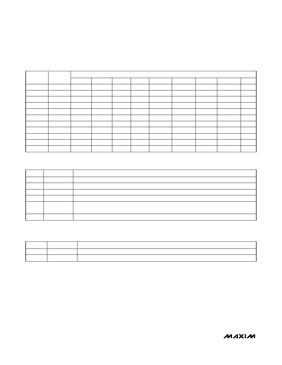
Table 5. Configuration 0 Register (Address: 0x01)
DATA
NAME
ADDRESS
BIT 7
BIT 6
BIT 5
BIT 4
BIT 3
BIT 2
BIT 1
BIT 0
MODE
CONTRL
0x00
0
0
spioffsht
pllbw
shape
ckouts
ckouton
mode
R/W
CONFIG0
0x01
ckdiv[2]
ckdiv[1]
ckdiv[0]
cap[4]
cap[3]
cap[2]
cap[1]
cap[0]
R/W
HIFREQ1
0x02
fhi[15]
fhi[14]
fhi[13]
fhi[12]
fhi[11]
fhi[10]
fhi[9]
fhi[8]
R/W
HIFREQ0
0x03
fhi[7]
fhi[6]
fhi[5]
fhi[4]
fhi[3]
fhi[2]
fhi[1]
fhi[0]
R/W
LOFREQ1
0x04
flo[15]
flo[14]
flo[13]
flo[12]
flo[11]
flo[10]
flo[9]
flo[8]
R/W
LOFREQ0
0x05
flo[7]
flo[6]
flo[5]
flo[4]
flo[3]
flo[2]
flo[1]
flo[0]
R/W
FLOAD
0x06
—
—
—
—
—
—
—
fload
R/W
DATAIN
0x07
—
—
—
—
—
—
—
datain_bit
R/W
EN
0x08
—
—
—
—
—
—
—
enable_bit
R/W
CONFIG1
0x09
0
0
0
0
0
gposel[2]
gposel[1]
gposel[0]
R/W
STATUS
0x0C
fhi/lo[15]
fhi/lo[14]
fhi/lo[13] fhi/lo[12]
X
0
TxREADY
NoXTAL
R
Table 3. Register Configuration
BIT
NAME
FUNCTION
0
mode
ASK(0) or FSK(1)
1
ckouton
Crystal clock output enable(1) on GPO output
2
ckouts
Crystal clock output enable(1) while part is in shutdown mode
3
shape
Disable(0) or enable(1) transmitter envelope-shaping resistor
4
pllbw
PLL bandwidth setting, low(0) = 300kHz or high(1) = 600kHz; 300kHz is recommended for fractional-N
and 600kHz for fixed-N
5
spioffsht
Enable(0) or disable(1) SPI communication during shutdown
Table 4. Control Register (Address: 0x00)