Rainbow Electronics MAX19997A User Manual
Page 8
MAX19997A
Dual, SiGe High-Linearity, 1800MHz to 2900MHz
Downconversion Mixer with LO Buffer
8
_______________________________________________________________________________________
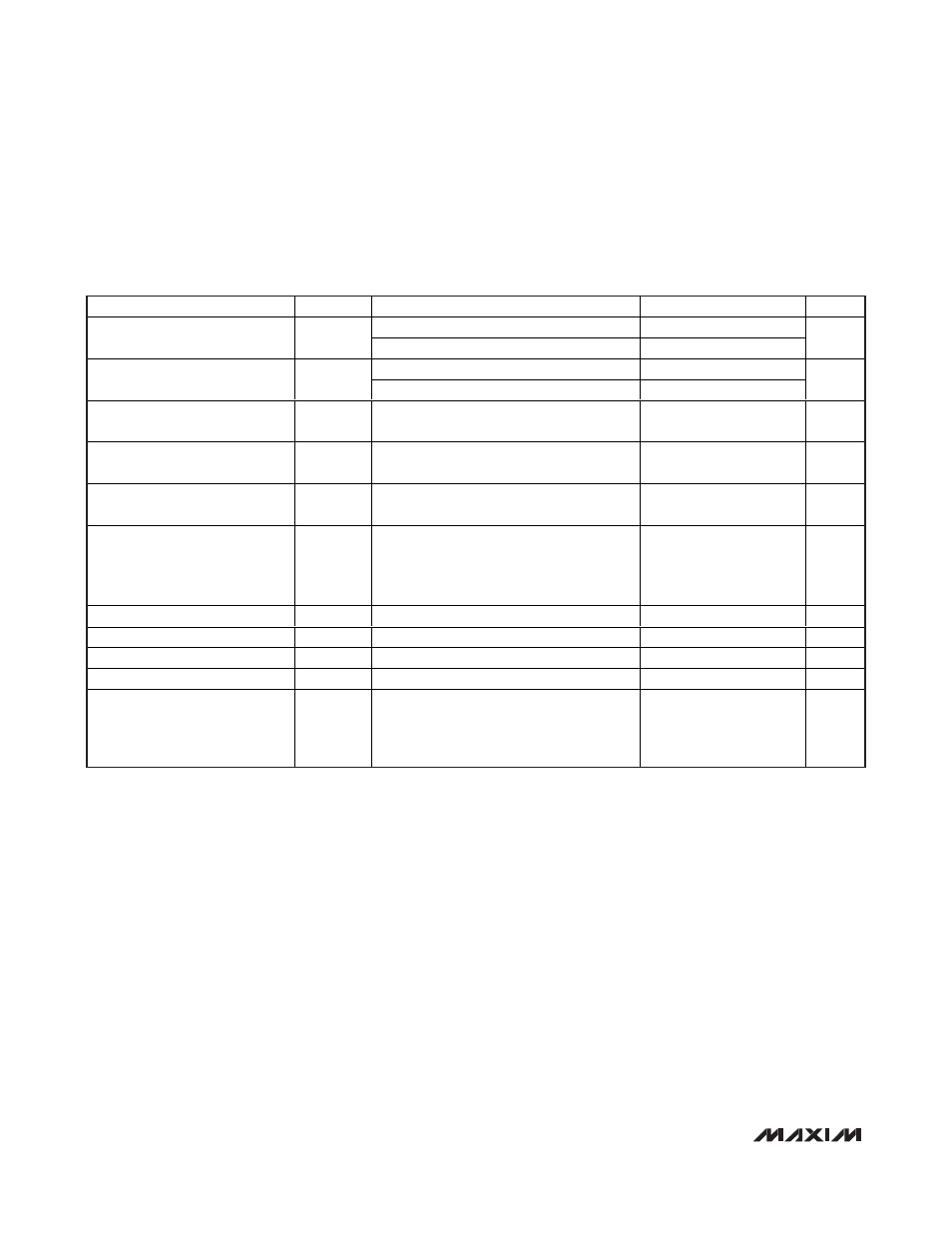
+3.3V SUPPLY, LOW-SIDE LO INJECTION AC ELECTRICAL CHARACTERISTICS
(continued)
(
Typical Application Circuit optimized for the standard RF band (see Table 1). Typical values are at V
CC
= +3.3V, P
RF
= -5dBm,
P
LO
= 0dBm, f
RF
= 2600MHz, f
LO
= 2250MHz, f
IF
= 350MHz, T
C
= +25°C, unless otherwise noted.) (Note 7)
PARAMETER
SYMBOL
CONDITIONS
MIN
TYP
MAX
UNITS
P
RF
= -10dBm, f
SPUR
= f
LO
+ 175MHz
74
2RF-2LO Spur
2 x 2
P
RF
= -5dBm, f
SPUR
= f
LO
+ 175MHz
69
dBc
P
RF
= -10dBm, f
SPUR
= f
LO
+ 116.67MHz
74
3RF-3LO Spur
3 x 3
P
RF
= -5dBm, f
SPUR
= f
LO
+ 116.67MHz
64
dBc
RF Input Return Loss
LO on and IF terminated into a matched
impedance
16
dB
LO Input Return Loss
RF and IF terminated into a matched
impedance
11
dB
IF Output Impedance
Z
IF
Nominal differential impedance at the IC’s
IF outputs
200
Ω
IF Output Return Loss
RF terminated into 50
Ω, LO driven by 50Ω
source, IF transformed to 50
Ω using
external components shown in the Typical
Application Circuit
26
dB
RF-to-IF Isolation
25
dB
LO Leakage at RF Port
-36
dBm
2LO Leakage at RF Port
-31
dBm
LO Leakage at IF Port
-13.5
dBm
Channel Isolation
RFMAIN (RFDIV) converted power
measured at IFDIV (IFMAIN) relative to
IFMAIN (IFDIV), all unused ports terminated
to 50
Ω
42
dB
Note 5:
Operation outside this range is possible, but with degraded performance of some parameters. See the
Typical Operating
Characteristics.
Note 6:
Not production tested.
Note 7:
All limits reflect losses of external components, including a 0.8dB loss at f
IF
= 350MHz due to the 4:1 impedance trans-
former. Output measurements taken at the IF outputs of
Typical Application Circuit.
Note 8:
Guaranteed by design and characterization.
Note 9:
100% production tested for functional performance.
Note 10: RF frequencies below 2400MHz require external RF tuning similar to components listed in Table 2.
Note 11: Maximum reliable continuous input power applied to the RF or IF port of this device is +12dBm from a 50
Ω source.
Note 12: Measured with external LO source noise filtered so the noise floor is -174dBm/Hz. This specification reflects the effects of
all SNR degradations in the mixer, including the LO noise as defined in Application Note 2021:
Specifications and
Measurement of Local Oscillator Noise in Integrated Circuit Base Station Mixers.