Rainbow Electronics MAX19997A User Manual
Page 31
MAX19997A
Dual, SiGe High-Linearity, 1800MHz to 2900MHz
Downconversion Mixer with LO Buffer
______________________________________________________________________________________
31
DESIGNATION
QTY
DESCRIPTION
COMPONENT SUPPLIER
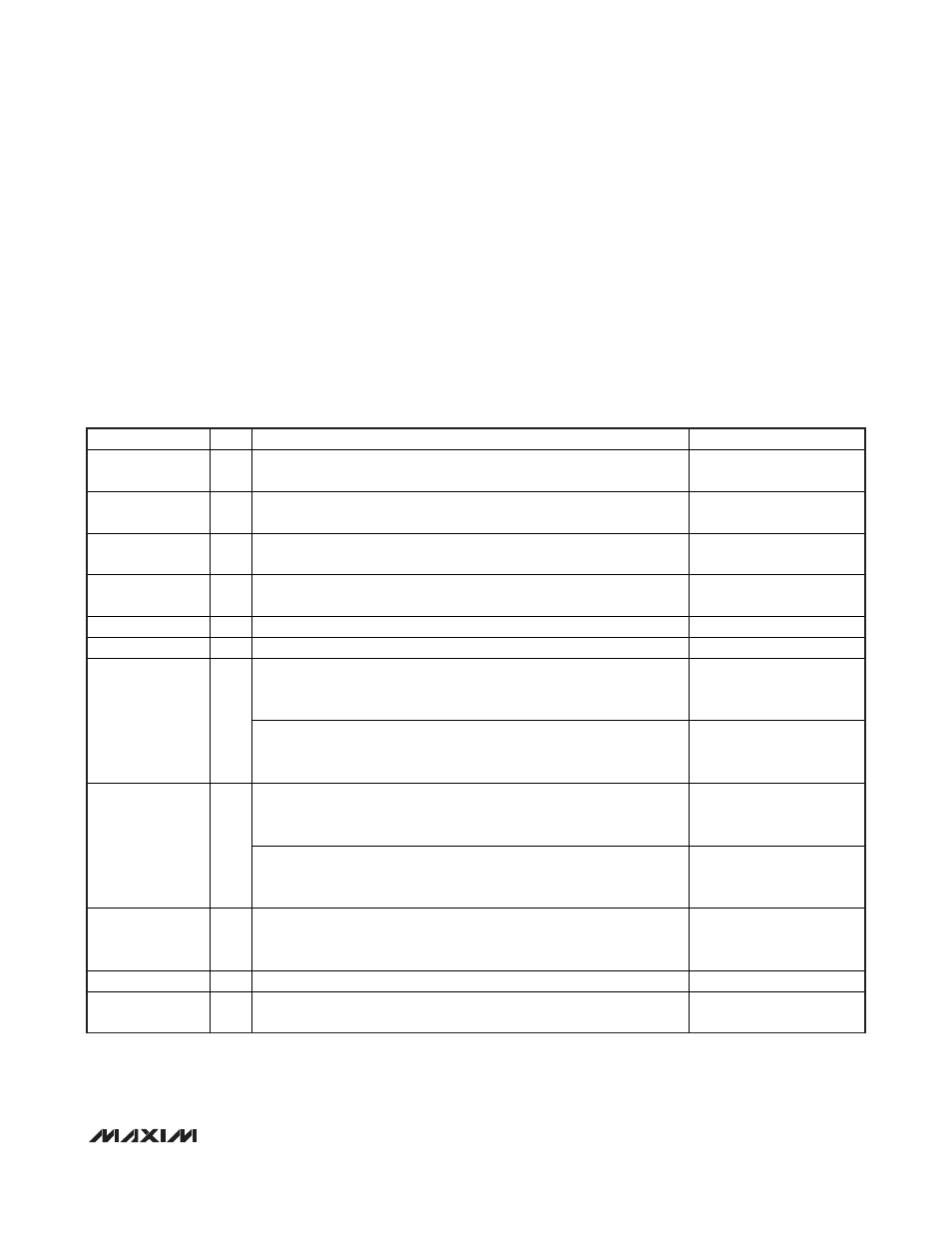
C1, C8
2
22pF microwave capacitors (0402)
Murata Electronics North
America, Inc.
C14
1
1.5pF microwave capacitor (0402)
Murata Electronics North
America, Inc.
C4, C9, C13, C15,
C17, C18
6
0.01µF microwave capacitors (0402)
Murata Electronics North
America, Inc.
C10, C11, C12,
C19, C20, C21
6
82pF microwave capacitors (0603)
Murata Electronics North
America, Inc.
L1, L2, L3, L4
4
120nH wire-wound high-Q inductors* (0805)
Coilcraft, Inc.
L7, L8
0
Not used
—
750
Ω ±1% resistors (0402). Use for V
CC
= +5.0V applications. Larger
values can be used to reduce power at the expense of some
performance loss. See the Typical Operating Characteristics section.
Digi-Key Corp.
R1, R4
2
1.1k
Ω ±1% resistors (0402). Use for V
CC
= +3.3V applications. Larger
values can be used to reduce power at the expense of some
performance loss. See the Typical Operating Characteristics section.
Digi-Key Corp.
698
Ω ±1% resistors (0402). Use for V
CC
= +5.0V applications. Larger
values can be used to reduce power at the expense of some
performance loss. See the Typical Operating Characteristics section.
Digi-Key Corp.
R2, R5
2
845
Ω ±1% resistors (0402). Use for V
CC
= +3.3V applications. Larger
values can be used to reduce power at the expense of some
performance loss. See the Typical Operating Characteristics section.
Digi-Key Corp.
R3, R6
2
0
Ω resistors (1206). These resistors can be increased in value to reduce
power dissipation in the device, but reduces the compression point. Full
P
1dB
performance achieved using 0
Ω.
Digi-Key Corp.
T1, T2
2
4:1 IF baluns (TC4-1W-17+)
Mini-Circuits
U1
1
MAX19997A IC (36 TQFN-EP)
Maxim Integrated Products,
Inc.
Table 1. Standard RF Band Application Circuit Component Values (Optimized for
Frequencies Ranging from 2400MHz to 2900MHz)
*
Use 390nH (0805) inductors for an IF frequency of 200MHz. Contact the factory for details.
Power-Supply Bypassing
Proper voltage supply bypassing is essential for high-
frequency circuit stability. Bypass each V
CC
pin with
the capacitors shown in the
Typical Application Circuit
.
Exposed Pad RF/Thermal Considerations
The exposed pad (EP) of the MAX19997A’s 36-pin thin
QFN-EP package provides a low thermal-resistance
path to the die. It is important that the PCB on which the
MAX19997A is mounted be designed to conduct heat
from the EP. In addition, provide the EP with a low-
inductance path to electrical ground. The EP MUST be
soldered to a ground plane on the PCB, either directly
or through an array of plated via holes.