Rainbow Electronics MAX98089 User Manual
Page 82
���������������������������������������������������������������� Maxim Integrated Products 82
MAX98089
Low-Power, Stereo Audio Codec
with FlexSound Technology
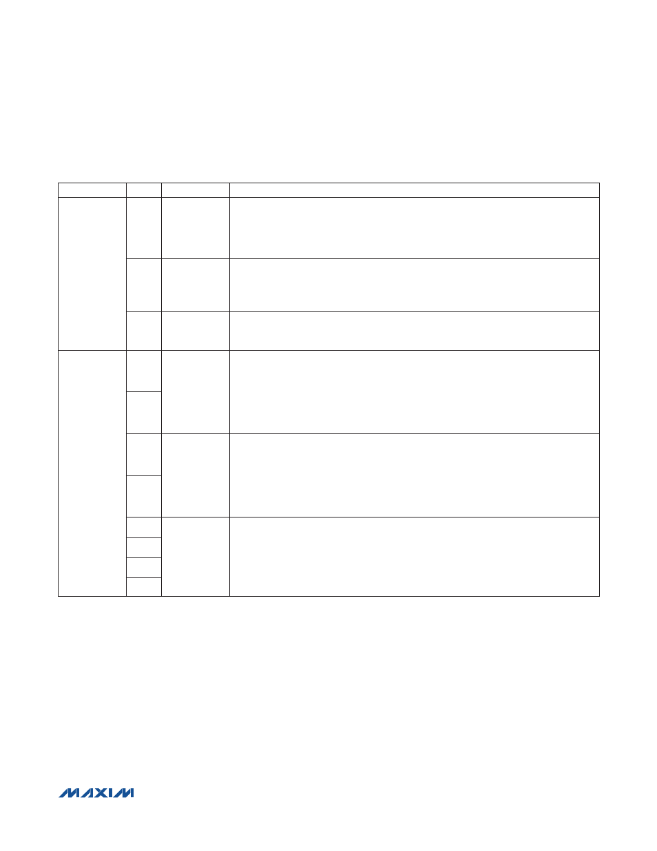
Table 10. Digital Audio Interface Registers (continued)
REGISTER
BIT
NAME
DESCRIPTION
0x16/0x1E
2
HIZOFF1/
HIZOFF2
Disable DA1/DAI2 Output High-Impedance Mode
Normally SDOUT is set high impedance between data words. Set HIZOFF1/HIZOFF2 to
force a level on SDOUT at all times.
0 = Disabled
1 = Enabled
1
SDOEN1/
SDOEN2
DAI1/DAI2 Record Path Output Enable
DAI2 outputs data only if LBEN1 = 1.
0 = Disabled
1 = Enabled
0
SDIEN1/
SDIEN2
DAI1/DAI2 Playback Path Input Enable
0 = Disabled
1 = Enabled
0x17/0x1F
7
SLOTL1/
SLOTL2
TDM Left Time Slot
Selects which of the four slots is used for left data on DAI1/DAI2. If the same slot is
selected for left and right audio, left audio is placed in the slot.
00 = Slot 1
01 = Slot 2
10 = Slot 3
11 = Slot 4
6
5
SLOTR1/
SLOTR2
TDM Right Time Slot
Selects which of the four slots is used for right data on DAI1/DAI2. If the same slot is
selected for left and right audio, left audio is placed in the slot.
00 = Slot 1
01 = Slot 2
10 = Slot 3
11 = Slot 4
4
3
SLOTDLY1/
SLOTDLY2
TDM Slot Delay
Adds 1 BCLK cycle delay to the data in the specified TDM slot.
1xxx = Slot 4 delayed
x1xx = Slot 3 delayed
xx1x = Slot 2 delayed
xxx1 = Slot 1 delayed
2
1
0