Digital audio interfaces, Table 8. sidetone register – Rainbow Electronics MAX98089 User Manual
Page 78
���������������������������������������������������������������� Maxim Integrated Products 78
MAX98089
Low-Power, Stereo Audio Codec
with FlexSound Technology
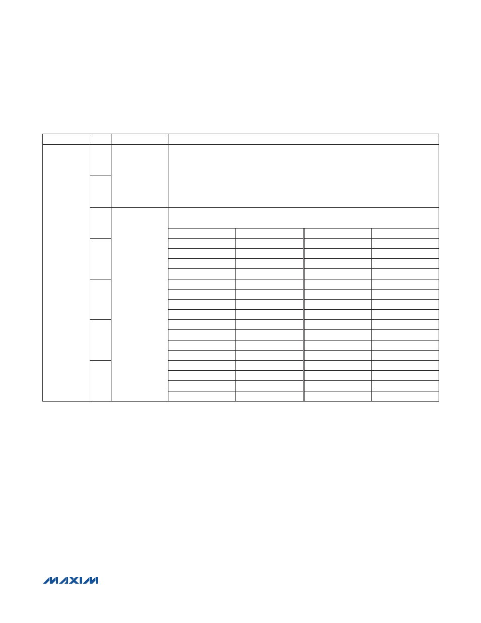
Table 8. Sidetone Register
IC implements sidetone digitally. Doing so helps prevent
unwanted feedback into the playback signal path and
better matches the playback audio signal.
Digital Audio Interfaces
The IC includes two separate playback signal paths and
one record signal path. Digital audio interface 1 (DAI1)
is used to transmit the recorded stereo audio signal and
receive a stereo audio signal for playback. Digital audio
interface 2 (DAI2) is used to receive a second stereo
audio signal. Use DAI1 for all full-duplex operations and
for all voice signals. Use DAI2 for music and to mix two
playback audio signals. The digital audio interfaces are
separate from the audio ports to enable either interface
to communicate with any external device connected to
either audio port.
Each audio interface can be configured in a variety of for-
mats including left justified, I
2
S, PCM, and time division
multiplexed (TDM). TDM mode supports up to 4 mono
audio slots in each frame. The IC can use up to 2 mono
slots per interface, leaving the remaining two slots avail-
able for another device. Table 9 shows how to configure
the device for common digital audio formats. Figures 16
and 17 show examples of common audio formats. By
default, SDOUTS1 and SDOUTS2 are set high imped-
ance when the IC is not outputting data to facilitate shar-
ing the bus. Configure the interface in TDM mode using
only slot 1 to transmit and receive mono PCM voice data.
The IC’s digital audio interfaces support both ADC to DAC
loop-through and digital loopback. Loop-through allows
the signal converted by the ADC to be routed to the DAC
for playback. The signal is routed from the record path to
REGISTER
BIT
NAME
DESCRIPTION
0x2E
7
DSTS
Sidetone Source
Selects which ADC output is fed back as sidetone. When mixing the left and right ADC
outputs, each is attenuated by 6dB to prevent full-scale signals from clipping.
00 = Sidetone disabled
01 = Left ADC
10 = Right ADC
11 = Left + Right ADC
6
4
DVST
Sidetone Level
Adjusts the sidetone signal level. All levels are referenced to the ADC’s full-scale output.
VALUE
LEVEL (dB)
VALUE
LEVEL (dB)
3
0x00
Sidetone disabled
0x10
-30.5
0x01
-0.5
0x11
-32.5
0x02
-2.5
0x12
-34.5
0x03
-4.5
0x13
-36.5
2
0x04
-6.5
0x14
-38.5
0x05
-8.5
0x15
-40.5
0x06
-10.5
0x16
-42.5
0x07
-12.5
0x17
-44.5
1
0x08
-14.5
0x18
-46.5
0x09
-16.5
0x19
-48.5
0x0A
-18.5
0x1A
-50.5
0x0B
-20.5
0x1B
-52.5
0
0x0C
-22.5
0x1C
-54.5
0x0D
-24.5
0x1D
-56.6
0x0E
-26.5
0x1E
-58.5
0x0F
-28.5
0x1F
-60.5