Table 3. microphone input registers – Rainbow Electronics MAX98089 User Manual
Page 70
���������������������������������������������������������������� Maxim Integrated Products 70
MAX98089
Low-Power, Stereo Audio Codec
with FlexSound Technology
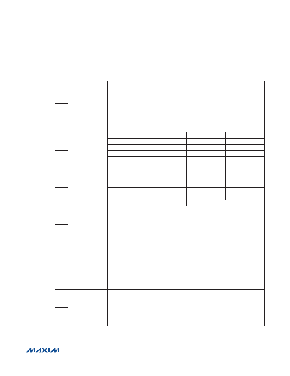
Table 3. Microphone Input Registers
REGISTER
BIT
NAME
DESCRIPTION
0x35/0x36
6
PA1EN/PA2EN
MIC1/MIC2 Preamplifier Gain
Course microphone gain adjustment.
00 = Preamplifier disabled
01 = 0dB
10 = 20dB
11 = 30dB
5
4
PGAM1/PGAM2
MIC1/MIC2 PGA
Fine microphone gain adjustment.
3
VALUE
GAIN (dB)
VALUE
GAIN (dB)
0x00
+20
0x0B
+9
0x01
+19
0x0C
+8
2
0x02
+18
0x0D
+7
0x03
+17
0x0E
+6
0x04
+16
0x0F
+5
1
0x05
+15
0x10
+4
0x06
+14
0x11
+3
0x07
+13
0x12
+2
0
0x08
+12
0x13
+1
0x09
+11
0x14 to 0x1F
0
0x0A
+10
0x48
7
MICCLK
Digital Microphone Clock Frequency
Select a frequency that is within the digital microphone’s clock frequency range. Set
OSR1 = 1 when using a digital microphone.
00 = PCLK/8
01 = PCLK/6
10 = 64 x LRCLK
11 = Reserved
6
5
DIGMICL
Left Digital Microphone Enable
Set PA1EN = 00 for proper operation.
0 = Disabled
1 = Enabled
4
DIGMICR
Right Digital Microphone Enable
Set PA1EN = 00 for proper operation.
0 = Disabled
1 = Enabled
1
EXTMIC
External Microphone Connection
Routes INA_/EXTMIC_ to the microphone preamplifiers. Set INAEN = 0 when using
INA_/EXTMIC_ as a microphone input.
00 = Disabled
01 = MIC1 input
10 = MIC2 input
11 = Reserved
0