Filterless class d operation, Rf susceptibility, Startup/shutdown sequencing – Rainbow Electronics MAX98089 User Manual
Page 123: Table 38. example startup sequence
��������������������������������������������������������������� Maxim Integrated Products 123
MAX98089
Low-Power, Stereo Audio Codec
with FlexSound Technology
Filterless Class D Operation
Traditional Class D amplifiers require an output filter to
recover the audio signal from the amplifier’s output. The
filters add cost, increase the solution size of the amplifier,
and can decrease efficiency and THD+N performance.
The traditional PWM scheme uses large differential output
swings (2 x V
DD
peak to peak) and causes large ripple
currents. Any parasitic resistance in the filter components
results in a loss of power, lowering the efficiency.
The IC does not require an output filter. The device relies
on the inherent inductance of the speaker coil and the
natural filtering of both the speaker and the human ear
to recover the audio component of the square-wave out-
put. Eliminating the output filter results in a smaller, less
costly, more efficient solution.
Because the frequency of the IC’s output is well beyond
the bandwidth of most speakers, voice coil movement
due to the square-wave frequency is very small. Although
this movement is small, a speaker not designed to handle
the additional power can be damaged. For optimum
results, use a speaker with a series inductance > 10FH.
Typical 8I speakers exhibit series inductances in the
20FH to 100FH range.
RF Susceptibility
GSM radios transmit using time-division multiple access
(TDMA) with 217Hz intervals. The result is an RF signal
with strong amplitude modulation at 217Hz and its har-
monics that is easily demodulated by audio amplifiers.
The IC is designed specifically to reject RF signals; how-
ever, PCB layout has a large impact on the susceptibility
of the end product.
In RF applications, improvements to both layout and com-
ponent selection decrease the IC’s susceptibility to RF
noise and prevent RF signals from being demodulated into
audible noise. Trace lengths should be kept below 1/4 of
the wavelength of the RF frequency of interest. Minimizing
the trace lengths prevents them from functioning as anten-
nas and coupling RF signals into the IC. The wavelength
(
l) in meters is given by: l = c/f where c = 3 x 10
8
m/s, and
f = the RF frequency of interest.
Route audio signals on middle layers of the PCB to allow
ground planes above and below to shield them from RF
interference. Ideally, the top and bottom layers of the
PCB should primarily be ground planes to create effec-
tive shielding.
Additional RF immunity can also be obtained by rely-
ing on the self-resonant frequency of capacitors as it
exhibits a frequency response similar to a notch filter.
Depending on the manufacturer, 10pF to 20pF capaci-
tors typically exhibit self resonance at the RF frequencies
of interest. These capacitors, when placed at the input
pins, can effectively shunt the RF noise to ground. For
these capacitors to be effective, they must have a low-
impedance, low-inductance path to the ground plane.
Avoid using microvias to connect to the ground plane
whenever possible as these vias do not conduct well at
RF frequencies.
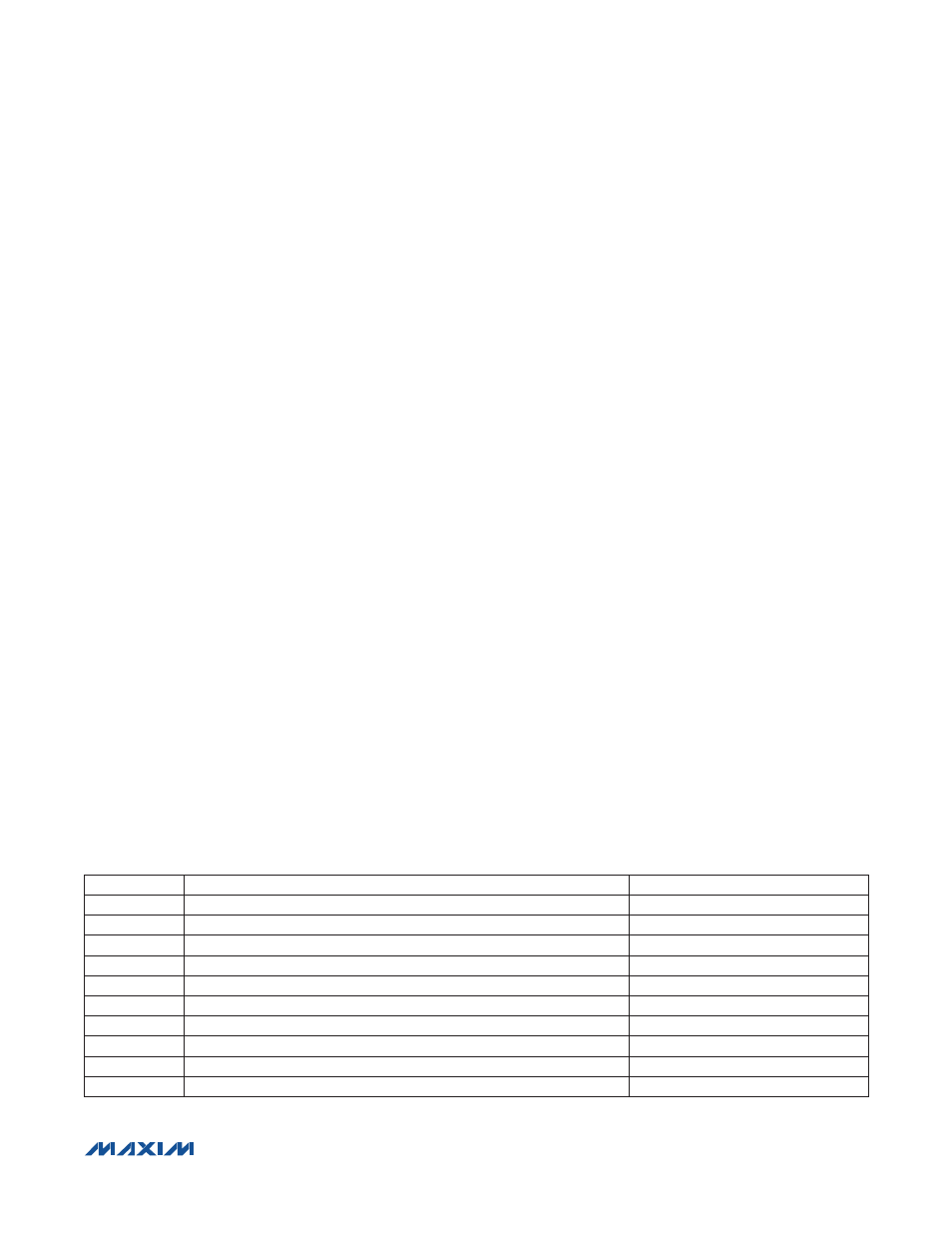
Startup/Shutdown Sequencing
To ensure proper device initialization and minimal click-
and-pop, program the IC’s SHDN = 1 after configuring all
registers. Table 38 lists an example startup sequence for
the device. To shut down the IC, simply set SHDN = 0.
Table 38. Example Startup Sequence
SEQUENCE
DESCRIPTION
REGISTERS
1
Ensure SHDN = 0
0x51
2
Configure clocks
0x10 to 0x13, 0x19 to 0x1B
3
Configure digital audio interface
0x14 to 0x17, 0x1C to 0x1F
4
Configure digital signal processing
0x18, 0x20, 0x3F to 0x46
5
Load coefficients
0x52 to 0xC9
6
Configure mixers
0x22 to 0x2D
7
Configure gain and volume controls
0x2E to 0x3E
8
Configure miscellaneous functions
0x47 to 0x4B
9
Enable desired functions
0x4C, 0x50
10
Set SHDN = 1
0x51