Microphone inputs, Figure 6. microphone input block diagram – Rainbow Electronics MAX98089 User Manual
Page 69
���������������������������������������������������������������� Maxim Integrated Products 69
MAX98089
Low-Power, Stereo Audio Codec
with FlexSound Technology
Microphone Inputs
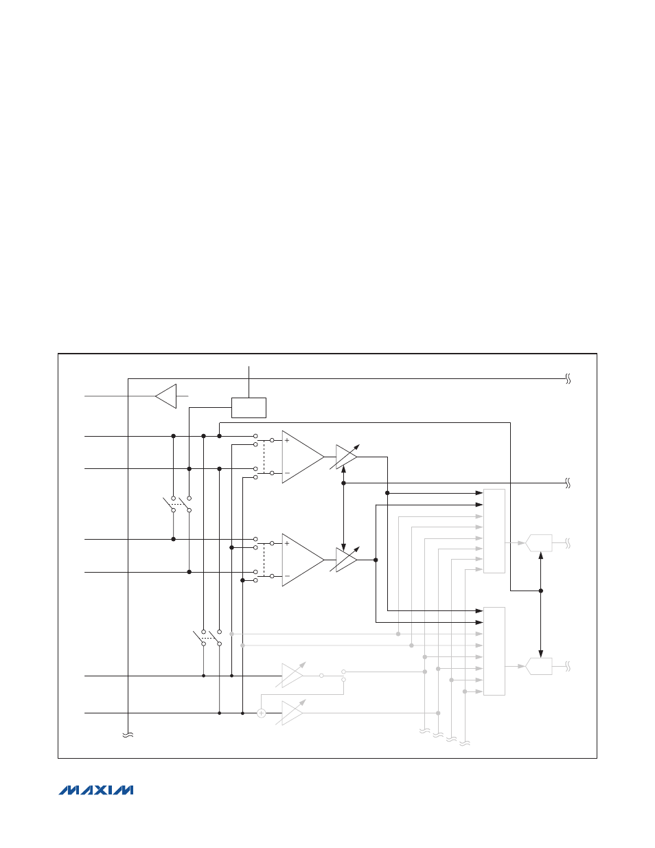
The device includes three differential microphone inputs
and a low-noise microphone bias for powering the micro-
phones (Figure 6). One microphone input can also be con-
figured as a digital microphone input accepting signals
from up to two digital microphones. Any two microphones,
analog or digital, can be recorded simultaneously.
In the typical application, one microphone input is used
for the handset microphone and the other is used as an
accessory microphone. In systems using a background
noise microphone, INA can be retasked as another
microphone input.
In systems where the codec is not the only device
recording microphone signals, connect microphones to
MIC2P/MIC2N and EXTMICP/EXTMICN. MIC1P/MIC1N
then become outputs that route the microphone signals
to an external device as needed. Two devices can then
record microphone signals without needing external
analog switches.
Analog microphone signals are amplified by two stages
of gain and then routed to the ADCs. The first stage offers
selectable 0dB, 20dB, or 30dB settings. The second
stage is a programmable-gain amplifier (PGA) adjustable
from 0dB to 20dB in 1dB steps. To maximize the signal-
to-noise ratio, use the gain in the first stage whenever
possible. Zero-crossing detection is included on the PGA
to minimize zipper noise while making gain changes.
Figure 6. Microphone Input Block Diagram
MIC1P/
DIGMICDATA
MICBIAS
MBEN
MCLK
REG
MIC1N/
DIGMICCLK
MIC2BYP
INABYP
EXTMIC
PA1EN:
0/20/30dB
PGAM1:
+20dB TO 0dB
MIX
MIX
MIXADL
MIXADR
ADCL
EXTMIC
PA2EN:
0/20/30dB
PGAINA:
+20dB TO -6dB
PGAINA:
+20dB TO -6dB
MIC2P
MIC2N
INA1/EXTMICP
PGAM1:
+20dB TO 0dB
AGC CONTROL
INADIFF
ADLEN
ADREN
INA2/EXTMICN
ADCR
CLOCK
CONTROL