Line inputs, Figure 7. line input block diagram, Figure 8. summing multiple input signals – Rainbow Electronics MAX98089 User Manual
Page 71: Table 3. microphone input registers (continued)
���������������������������������������������������������������� Maxim Integrated Products 71
MAX98089
Low-Power, Stereo Audio Codec
with FlexSound Technology
Table 3. Microphone Input Registers (continued)
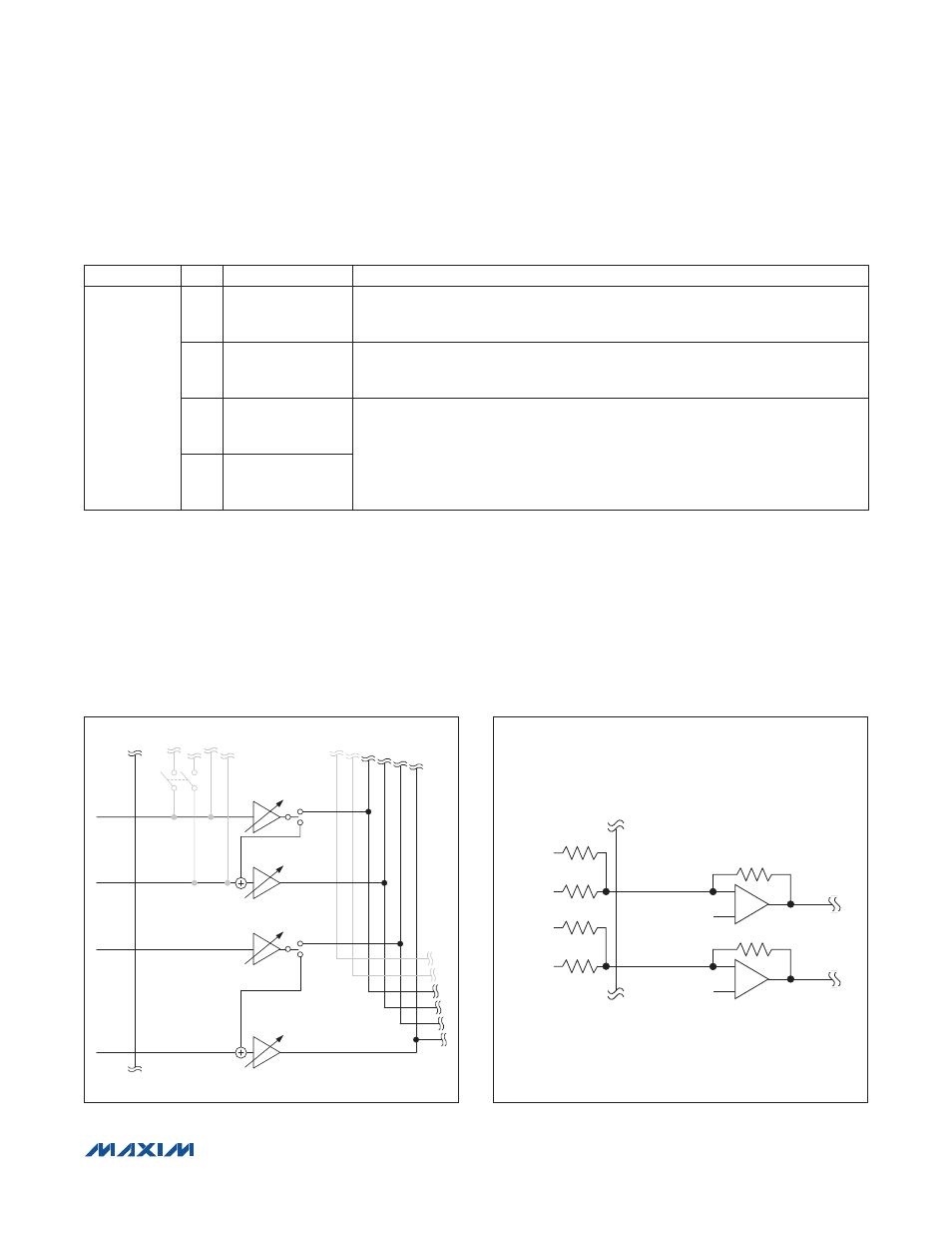
Line Inputs
The device includes two sets of line inputs (Figure 7).
Each set can be configured as a stereo single-ended
input or as a mono differential input. Each input includes
adjustable gain to match a wide range of input signal
levels. If a custom gain is needed, the external gain
mode provides a trimmed feedback resistor. Set the gain
by choosing the appropriate input resistor and using the
following formula:
AV
PGAIN
= 20 x log (20kI/R
IN
)
The external gain mode also allows summing multiple
signals into a single input, by connecting multiple input
resistors as show in Figure 8, and/or inputting signals
larger than 1V
P-P
by adjusting the ration of the 20kI/R
IN
less than 1.
Figure 7. Line Input Block Diagram
Figure 8. Summing Multiple Input Signals into INA/INB
INADIFF
PGAINA:
+20dB TO -6dB
INABYP
INBDIFF
INA1/
EXTMICP
INA2/
EXTMICN
INB1
INB2
PGAINA:
+20dB TO -6dB
PGAINB:
+20dB TO -6dB
PGAINB:
+20dB TO -6dB
LEFT
INPUT 1
LEFT
INPUT 2
INA1/EXTMICP
VCM
INA2/EXTMICN
20kI
1V
P-P
(max)
1V
P-P
(max)
RIGHT
INPUT 1
RIGHT
INPUT 2
VCM
20kI
REGISTER
BIT
NAME
DESCRIPTION
0x4A
7
INABYP
INA�/EXTMIC� to MIC1� Bypass Switch
0 = Disabled
1 = Enabled
4
MIC2BYP
MIC1� to MIC2� Bypass Switch
0 = Disabled
1 = Enabled
1
RECBYP
See the Output Bypass Switches section.
0
SPKBYP