Record path signal processing, Microphone agc, Noise gate – Rainbow Electronics MAX98089 User Manual
Page 73: Figure 10. record path signal processing, Table 5. adc input mixer register, Microphone agc noise gate
���������������������������������������������������������������� Maxim Integrated Products 73
MAX98089
Low-Power, Stereo Audio Codec
with FlexSound Technology
Record Path Signal Processing
The device’s record signal path includes both automatic
gain control (AGC) for the microphone inputs and a digi-
tal noise gate at the output of the ADC (Figure 10).
Microphone AGC
The IC’s AGC monitors the signal level at the output of the
ADC and then adjusts the MIC1 and MIC2 analog PGA
settings automatically. When the signal level is below
the predefined threshold, the gain is increased up to its
maximum (20dB). If the signal exceeds the threshold,
the gain is reduced to prevent the output signal level
exceeding the threshold. When AGC is enabled, the
microphone PGA is not user programmable. The AGC
provides a more constant signal level and improves the
available ADC dynamic range.
Noise Gate
Since the AGC increases the levels of all signals below
a user-defined threshold, the noise floor is effectively
increased by 20dB. To counteract this, the noise gate
reduces the gain at low signal levels. Unlike typical noise
gates that completely silence the output below a defined
level, the noise gate in the IC applies downward expan-
sion. The noise gate attenuates the output at a rate of
1dB for each 2dB the signal is below the threshold with a
maximum attenuation of 12dB.
The noise gate can be used in conjunction with the AGC
or on its own. When the AGC is enabled, the noise gate
reduces the output level only when the AGC has set the
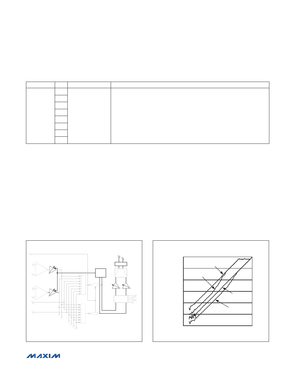
gain to the maximum setting. Figure 11 shows the gain
response resulting from using the AGC and noise gate.
Table 5. ADC Input Mixer Register
Figure 10. Record Path Signal Processing Block Diagram
Figure 11. AGC and Noise Gate Input vs. Output Gain
PGAM2:
+20dB TO 0dB
PGAM1:
+20dB TO -6dB
MIXADR
MIX
PA2EN:
0/20/30dB
PA1EN:
0/20/30dB
MIXADL
MIX
ADREN
ADLEN
ADCR
ADCL
AUTOMATIC
GAIN
CONTROL
NOISE GATE
MODE1
AVFLT
SRMIX_
MODE
AVLG: 0/6/
12/18dB
AVL:0dB
TO -15dB
AVRG: 0/6/
12/18dB
AVR:0dB
TO -15dB
AUDIO/
VOICE
FILTERS
SAMPLE RATE
CONVERTER
AGC AND NOISE GATE
AMPLITUDE RESPONSE
INPUT AMPLITUDE (dBFS)
AGC ONLY
AGC AND NOISE GATE
NOISE GATE ONLY
AGC AND NOISE
GATE DISABLED
OUTPUT AMPLITUDE (dBFS)
-20
-40
-60
-80
-100
-120
-100
-80
-60
-40
-20
0
-120
0
REGISTER
BIT
NAME
DESCRIPTION
0x23/0x24
7
MIXADL/MIXADR
Left/Right ADC Input Mixer
Selects which analog inputs are recorded by the left/right ADC.
1xxxxxxx = MIC1
x1xxxxxx = MIC2
xx1xxxxx = INA1 pin direct
xxx1xxxx = INA2 pin direct
xxxx1xxx = INA1
xxxxx1xx = INA2 (INADIFF = 0) or INA2 - INA1 (INADIFF = 1)
xxxxxx1x = INB1
xxxxxxx1 = INB2 (INBDIFF = 0) or INB2 - INB1 (INBDIFF = 1)
6
5
4
3
2
1
0