Rainbow Electronics MAX9589 User Manual
General description, Applications, Features
General Description
The MAX9586–MAX9589 are small, low-power, multi-
channel video amplifiers with integrated reconstruction
filters and input clamps. Specially suited for standard-
definition video signals, these devices are ideal for a
wide range of television and set-top box applications.
The video signals from the outputs of a digital-to-analog
converter (DAC) are AC-coupled to the inputs of the
MAX9586–MAX9589. External video signals, in which
the DC bias is usually not known, can also be AC-cou-
pled to the inputs of the MAX9586–MAX9589. The input
sync-tip clamps set the DC level of composite video or
luma signals, and the input bias circuits set the DC
level of chroma signals.
The reconstruction filter typically has ±1dB passband
flatness at 7MHz and 62dB attenuation at 27MHz. The
amplifiers have 2V/V gain and the outputs can be DC-
coupled to a 75Ω load, which is the equivalent of two
video loads, or AC-coupled to a 150Ω load.
The MAX9586–MAX9589 operate from a 2.7V to 3.6V sin-
gle supply and are specified over the -40°C to +125°C
automotive temperature range. The MAX9586–MAX9589
are offered in small SOT23 and µMAX
®
packages.
Applications
Set-Top Boxes
Televisions
Features
♦ Single- (MAX9586), Dual- (MAX9587),
Triple- (MAX9588), and Quad- (MAX9589)
Channel Devices
♦ 7MHz, ±1dB Passband
♦ 62dB Attenuation at 27MHz
♦ Fixed Gain of 2V/V
♦ Low Power: 4.25mA per Channel
♦ 2.7V to 3.6V Single-Supply Operation
♦ Small SOT23 and µMAX Packages
MAX9586–MAX9589
Single, Dual, Triple, and Quad Standard-Definition
Video Filter Amplifiers with AC-Coupled Input Buffers
________________________________________________________________
Maxim Integrated Products
1
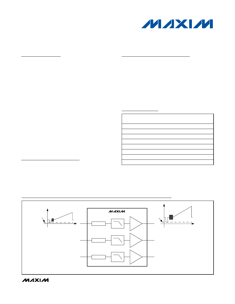
INA
OUTA
LPF
A
V
= 2V/V
MAX9588
UNKNOWN
BIAS
300mV
CLAMP
INB
OUTB
LPF
A
V
= 2V/V
CLAMP
INC
OUTC
LPF
A
V
= 2V/V
BIAS
Block Diagrams
19-0744; Rev 0; 2/07
For pricing, delivery, and ordering information, please contact Maxim/Dallas Direct! at
1-888-629-4642, or visit Maxim’s website at www.maxim-ic.com.
µMAX is a registered trademark of Maxim Integrated Products, Inc.
Ordering Information
Note: All devices are specified over the -40°C to +125°C operat-
ing temperature range.
+
Denotes a lead-free package.
*
Future product—contact factory for availability.
**
EP = Exposed paddle.
PART
PIN-
PACKAGE
CHANNELS
PKG
CODE
MAX9586AZK+T
5 Thin SOT23-5
1
Z5-1
MAX9586ATT+T*
6 TDFN-EP**
1
T633-2
MAX9587AZT+T*
6 Thin SOT23-6
2
Z6-1
MAX9587ALT+T*
6 µDFN-6
2
L622-1
MAX9588AUA+T*
8 µMAX-8
3
U8-1
MAX9588ALA+T*
8 µDFN-8
3
L822-1
MAX9589AUB+T*
10 µMAX-10
4
U10-2
MAX9589ATC+T*
12 TQFN-EP**
4
T1233-4
Block Diagrams continued at end of data sheet.
Pin Configurations and Selector Guide located at end of
data sheet.