Rf-tvmp40 tv wall mount, You’ll need – RocketFish RF-TVMP40 - User Manual User Manual
Page 14
14
Need help? Call 800-620-2790
RF-TVMP40 TV Wall Mount
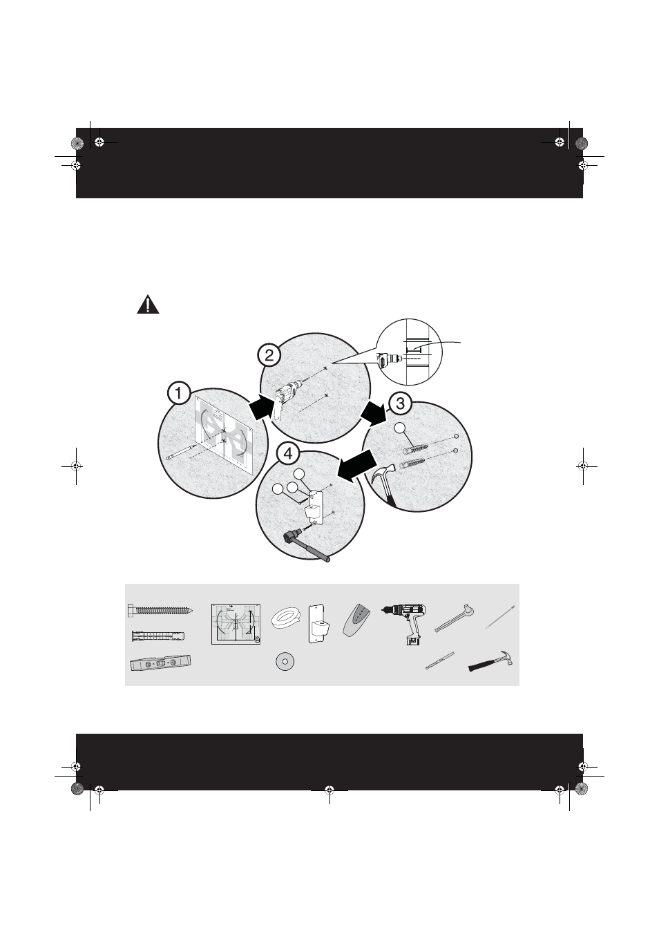
STEP 6 - Option 2: Installing on a solid concrete wall
1
Align the wall plate template (G) at the height you determined in the previous step and make sure that it is
level, then tape it to the wall. Use a pencil to mark the lag bolt hole locations (2). Remove the template.
2
Drill pilot holes to a depth of 2-3/4 in. (7 mm) using a 3/8 in. (10 mm) diameter masonry drill bit.
3
Insert the concrete wall anchors (W-C) into the pilot holes and use a hammer to make sure the anchors are
flush with the concrete surface.
4
Align the wall plate (D) with the anchors, insert the lag bolts (W-A) through the washers (W-B), then through
the holes in the wall plate, then tighten the lag bolts only until they are firm against the wall plate.
CAUTION: Avoid potential injuries or property damage!
DO NOT over-tighten the lag bolts (W-A).
You’ll need
W-A
D
W-B
W-C
2-3/4 in.
(70 mm)
Edge-to edge
stud finder
W-A (2)
Pencil
Drill
3/8" masonry drill bit
1/2" socket
wrench
Level
W-C (2)
Hammer
D Wall
plate
Centerline on Wood Stud or Concrete Wall
Centerline on Wood Stud or
Concrete Wall
Centerline on Wood Stud or
Concrete Wall
Center of TV Mount Plate
Center of TV Mount
Plate
Center of TV Mount
Plate
Center of TV Mount Plate
Center of TV Mount
Plate
Center of TV Mount
Plate
Center of TV Mount Plate
Center of TV Mount
Plate
Center of TV Mount
Plate
Center of TV Mount Plate
Center of TV Mount
Plate
Center of TV Mount
Plate
Center of TV Mount Plate
Center of TV Mount
Plate
Center of TV Mount
Plate
Center of TV Mount Plate
Center of TV Mount
Plate
Center of TV Mount
Plate
Wall Mount Bracket
Wall Mount
Bracket
Wall Mount
Bracket
Mounting Holes
Mounting
Holes
Mounting Holes
Arm (Center, left)
Arm (Center, left)
Arm (Center, left)
Arm (Up, left)
Arm (Up, left)
Arm (Up, left)
Arm (Up, right)
Arm (Up, right)
Arm (Up, right)
Arm (Down, left)
Arm (Down, left)
Arm (Down, left)
Arm (Down, right)
Arm (Down, right)
Arm (Down, right)
Arm (Center, right)
Arm (Center, right)
Arm (Center, right)
side
side
side
18.19" (462 mm) + Thickness of TV
18.19" (462 mm) + Thickness of TV
18.19" (462 mm) + Thickness of TV
24.5" (622 mm) + Thickness of TV
24.5" (622 mm) + Thickness of TV
24.5" (622 mm) + Thickness of TV
Distance from the Wall
Distance from the Wall
Distance from the Wall
10" (256 mm)
10" (256 mm)
10" (256 mm)
10" (256 mm)
10" (256 mm)
10" (256 mm)
13" (323 mm)
13" (323 mm)
13" (323 mm)
13" (323 mm)
13" (323 mm)
13" (323 mm)
17" (429 mm)
17" (429 mm)
17" (429 mm)
17" (429 mm)
17" (429 mm)
17" (429 mm)
Distance between mounting holes and center of TV when in horizontal position and pushed in against the wall.
Distance between mounting holes and center of TV when in horizontal position and pushed in against the wall.
Distance between mounting holes and center of TV when in horizontal position and pushed in against the wall.
LEFT TV ARC
“CENTER OF TV” can be placed at any
point along this arc line when the arm is
pushed in against the wall and mounted
at the centerline of your wood stud or
concrete wall.
LEFT TV ARC
“CENTER OF TV” can be placed at any
point along this arc line when the arm is
pushed in against the wall and mounted
at the centerline of your wood stud or
concrete wall.
LEFT TV ARC
“CENTER OF TV” can be placed at any
point along this arc line when the arm is
pushed in against the wall and mounted
at the centerline of your wood stud or
concrete wall.
RIGHT TV ARC
”CENTER OF TV” can be placed at any
point along this arc line when the Arm
is pushed in against the wall and
mounted at the centerline of your
Wood Stud or Concrete Wall.
RIGHT TV ARC
”CENTER OF TV” can be placed at any
point along this arc line when the Arm
is pushed in against the wall and
mounted at the centerline of your
Wood Stud or Concrete Wall.
RIGHT TV ARC
”CENTER OF TV” can be placed at any
point along this arc line when the Arm
is pushed in against the wall and
mounted at the centerline of your
Wood Stud or Concrete Wall.
7.68" (195 mm)
7.68" (195 mm)
7.68" (195 mm)
Vertical Space Requirements 20" (508 mm) + Height of TV*
Vertical Space Requirements 20" (508 mm) + Height of TV*
Vertical Space Requirements 20" (508 mm) + Height of TV*
V1 13-0239
Top
Dessus
Parte superior
RF-TVMP40 Template • Gabarit • Plantilla
Note
Remarque : Pour une construction à ossature de bois, localiser
d'abord les montants en bois, à l'aide d'un détecteur de montants.
Nota: para la instalación en construcciones de armazón de madera,
primero debe localizar las vigas de madera con un localizador de vigas.
Tools Needed
Outils nécessaires
Herramientas requeridas
Top
Dessus
Parte superior
G Template
Tape
W-B Washer (2)
RF-TVMP40_13-0238_MAN_V1_ENG.fm Page 14 Monday, April 15, 2013 1:26 PM