Levels half-bridge inverter stage, 60 a/57 a, Vishay semiconductors – C&H Technology EMF050J60U User Manual
Page 2
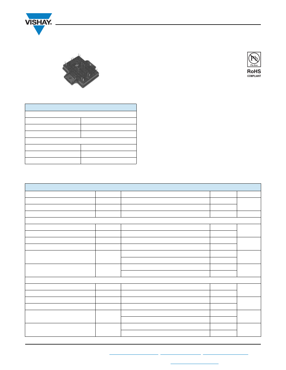
VS-EMF050J60U
www.vishay.com
Vishay Semiconductors
Revision: 09-Dec-11
1
Document Number: 93494
For technical questions within your region:
,
,
THIS DOCUMENT IS SUBJECT TO CHANGE WITHOUT NOTICE. THE PRODUCTS DESCRIBED HEREIN AND THIS DOCUMENT
ARE SUBJECT TO SPECIFIC DISCLAIMERS, SET FORTH AT
www.vishay.com/doc?91000
3-Levels Half-Bridge Inverter Stage, 60 A/57 A
FEATURES
• Warp1 and Warp2 PFC IGBT
• FRED Pt
®
and HEXFRED
®
antiparallel diodes
• FRED Pt
®
clamping diodes
• Integrated thermistor
• Square RBSOA
• Operating frequency 60 kHz to 150 kHz
• Low internal inductances
• Low switching loss
• Compliant to RoHS Directive 2002/95/EC
DESCRIPTION
VS-EMF050J60U is an integrated solution for a multi level
inverter half-bridge in a single package. The EMIPAK2
package is easy to use thanks to the solderable terminals
and provides improved thermal performance thanks to the
exposed substrate. The optimized layout also helps to
minimize stray parameters, allowing for better EMI
performance.
PRODUCT SUMMARY
1° LEVEL OF HALF-BRIDGE
V
CES
600 V
V
CE(ON)
typical at I
C
= 50 A
1.8 V
I
C
at T
C
= 98 °C
50 A
2° LEVEL OF HALF-BRIDGE
V
CES
900 V
V
CE(ON)
typical at I
C
= 50 A
2.73 V
I
C
at T
C
= 93 °C
50 A
EMIPAK2
ABSOLUTE MAXIMUM RATINGS
PARAMETER
SYMBOL
TEST CONDITIONS
MAX.
UNITS
Operating junction temperature
T
J
150
°C
Storage temperature range
T
Stg
- 40 to 125
RMS isolation voltage
V
ISOL
T
J
= 25 °C, all terminals shorted, f = 50 Hz, t = 1 s
3500
V
Q1 - Q4 IGBT
Collector to emitter voltage
V
CES
600
V
Gate to emitter voltage
V
GES
20
Pulsed collector current
I
CM
150
A
Clamped inductive load current
I
LM
(1)
150
Continuous collector current
I
C
T
C
= 25 °C
88
A
T
C
= 80 °C
60
Power dissipation
P
D
T
C
= 25 °C
338
W
T
C
= 80 °C
189
Q2 - Q3 IGBT
Collector to emitter voltage
V
CES
900
V
Gate to emitter voltage
V
GES
20
Pulsed collector current
I
CM
150
A
Clamped inductive load current
I
LM
(2)
150
Continuous collector current
I
C
T
C
= 25 °C
85
A
T
C
= 80 °C
57
Power dissipation
P
D
T
C
= 25 °C
338
W
T
C
= 80 °C
189