Hookup diagram: programming, Output configuration, Fig. 5 – Altronix FireSwitch108 Installation Instructions User Manual
Page 8
- 8 -
FireSwitch108
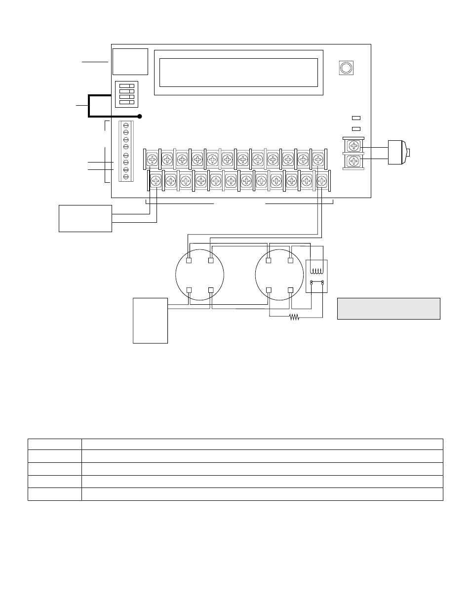
Hookup Diagram:
Programming:
To begin programming depress and hold down the joystick (approximately 2 secs.).
Note: If FireSwitch remains dormant for more than 90 secs. it will return to stand-by status screen.
Step 1. Setup outputs 1-8:
a. Select from: Class A, Class B or Aux. Outputs with or without battery backup (see chart below).
Output Configuration:
LCD Legend Function/Description
A
Class A output (Combines two (2) outputs, ex. 1-2, 3-4, 5-6, 7-8).
B
Class B output.
Ax
Aux. output with battery backup.
Bx
Aux. output without battery backup.
Depress the joystick one time from Stand-by screen.
Use [UP/DOWN] to select Function, Use [Left/Right] to select channel.
Magnetic
Door
Holder
Digital
Communicator
or Local
Annunciator
Dry output Contact
(Form "C" contacts)
Addressable
control module
trigger output
Special Application
Output selected
as Aux. Output
24VDC
Regulated
Power Limited
Output
+ --
4-wire Smoke
Detector
+ --
4-wire Smoke
Detector
Fire
Alarm
Control
Panel
(FACP)
EOL Power
Supervision Relay
(Not Supplied)
Refer to Appendix B for
Compatible Devices pgs. 18-19
EOL Resistor
from FACP
Factory Installed
Board Interface
Cable to
Power Supply
Ethernet
Power Limited
Power
Limited
INP1
RET1
INP2
RET2
OUT1 OUT2
OUT3
OUT4
OUT5
OUT6
OUT7
OUT8
+ SYNC
---
GF1
GF2
NC
NO
C
EA
RT
H
NEGA
TIV
E
POSITIV
E
INP2
INP1
INP2
INP1
ETHERNET
ON
RIGHT
LEFT
UP
DOWN
PRESS DOWN
FOR ENTER
+
24V
--
+
AUX
--
Fig. 5