No notification appliances allowed, Control circuit, System sensor – Altronix FireSwitch108 Installation Instructions User Manual
Page 14: Or cooperwheelock, Facp
- 14 - FireSwitch108
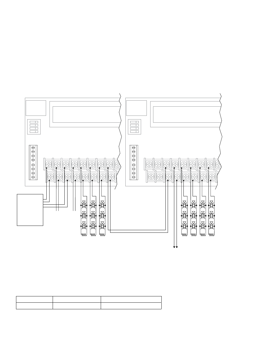
When connecting, keep wires on different sides of the screw terminals in order to maintain loop integrity supervision.
DO NOT LOOP CONTINUOUS WIRE AROUND THE SCREW.
Altronix Model
Max. Per Circuit
Max. Per FireSwitch108
FireSwitch108
32
128
FireSwitch Logic Board:
Programmed for desired Notification Appliance
FireSwitch Logic Board:
Programmed for Following INP2
FACP
(Fire Alarm
Control Panel)
No Notification
Appliances Allowed
10K
EOL
INP1
RET1
INP2
RET2
OUT1 OUT2
OUT3
OUT4
NEGA
TIV
E
POSITIV
E
INP2
INP1
INP2
INP1
ETHERNET
ON
10K
EOL
10K
EOL
Control Circuit
10K
EOL
INP1
RET1
INP2
RET2
OUT1 OUT2
OUT3
OUT4
NEGA
TIV
E
POSITIV
E
INP2
INP1
INP2
INP1
ETHERNET
ON
10K
EOL
10K
EOL
10K
EOL
To FireSwitch EOL
or next FireSwitch
A total of
twelve (12)
FireSwitch
Units can be
inter-connected
FACP
EOL
FACP
EOL
+ SYNC
---
NC
GND
NC
NO
C
EA
RT
H
+ SYNC
---
NC
GND
NC
NO
C
EA
RT
H
For continuous loop circuit use 10K
EOL, (Altronix Model # AL-EOL10).
5. Synchronizing NAC Power Extender Using Built-in Sync Protocol:
FireSwitch units include built-in protocols to support Amseco/Potter, Gentex
®
, System Sensor
®
or CooperWheelock
®
two-wire synchronizable devices, therefore an external sync module is not required (Output Programming Selection
Table, pg. 6). In these modes, Input 1 is always used to activate visual notification appliances (strobes), and Input 2 is
used to activate and silence audible notification appliances (strobes) (Table, pg. 6).
Note: Input 1 has to be activated in all the configurations.
6. Synchronizing multiple NAC Power Extender units (up to twelve):
Up to twelve (12) units can be synchronized using method 1 (Fig. 9, pg. 13) or method 2 up to four (4) units can be
synchronized (Fig. 10, pg. 14).
Fig. 9