Line neutral ground – Altronix FireSwitch108 Installation Instructions User Manual
Page 3
FireSwitch108
- 3 -
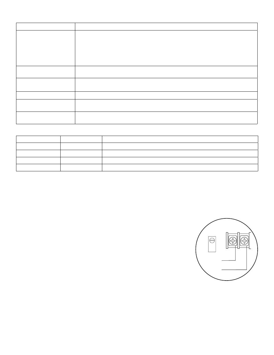
line
neutral
ground
L
N
Fig. 1
Power Supply Specifications:
AC Input
120VAC 60Hz, 4.8 amp.
Output
Eight (8) regulated supervised NAC output circuits, 24VDC, 2.5 amp maximum current.
10 amp max. total alarm current (configurable as Special Application Aux. ouputs).
7 amp max. stand-by without battery backup. 1 amp max with battery backup including
Aux. output. One (1) regulated aux. output rated at 24VDC @ 1 amp with battery backup
(see stand-by specifications below). 0.45 amp for Canadian applications. Total output
current in alarm condition must not exceed 10 amp.
Battery
Use two (2) 12VDC/12AH or two (2) 12VDC/7AH or two (2) 12VDC/40AH
batteries connected in series.
Stand-by/Alarm Current
Consumption
180mA/200mA
EOL Resistor (end of line) 10K (10,000 ohm), Altronix Model # AL-EOL10. (EOL10K-C for Canadian applications)
Ground fault maximum
test impedance
1000 ohm.
Maximum Loop
impedance
1 ohm.
Stand-by Specifications:
Stand-by Batteries
Stand-by/Alarm Aux. Current/Battery Back-up
24VDC/7AH
24 Hrs./5 mins.
No auxiliary current (battery backed up)
24VDC/12AH
24 Hrs./5 mins.
50mA auxiliary max. current (battery backed up)
24VDC/40AH
24 Hrs./5 mins.
1 amp auxiliary max. current (battery backed up)
24VDC/40AH
24 Hrs./30 mins.
0.45 amp auxiliary max. current (battery backed up) for Canadian Applications
Note: Unit is equipped with one (1) 1 amp max. auxiliary output (0.45 amp for Canadian applications): “AUX”
NAC outputs programmed for “AUX” with battery backup will remain battery backed up during power outage.
For loads connected to “AUX” please, refer to battery “Stand-by Specifications” above for ratings. When loads
are connected to the “AUX” output during alarm condition, and total current from AUX and remaining outputs
may not exceed total alarm current for the particular FireSwitch model. Aux outputs are not supervised.
To provide supervision use a UL Listed end of line relay or similar method.
Installation Instructions:
Wiring methods shall be in accordance with the National Electrical Code
NFPA 70/NFPA 72/ANSI/Canadian Electrical Code/CAN/ULC-S524/ULC-S527/ULC-S537
and with all local codes and authorities having jurisdiction.
Product is intended for indoor dry use only.
Carefully review:
Power Supply Specifications
(pg. 3)
Stand-by Specifications
(pg. 3)
Terminal Identification
(pgs. 5-6)
LED Diagnostics
(pg. 6)
Programming
(pgs. 8-11)
Testing and Maintenance
(pgs. 11-12)
1. Mount the unit in desired location. Mark and predrill holes in the wall to line up with
the top two keyholes in the enclosure. Install two upper fasteners and screws in the wall
with the screw heads protruding. Place the enclosure’s upper keyholes over the two upper screws, level and secure.
Mark the position of the lower two holes. Remove the enclosure. Drill the lower holes and install the two fasteners.
Place the enclosure’s upper keyholes over the two upper screws. Install the two lower screws and make sure to
tighten all screws (Enclosure Dimensions, pg. 20). Secure enclosure to earth ground (Fig. 1, pg. 3). Small terminal
block wire gauges range from 16 AWG to 22 AWG, all others range from 12 AWG to 22 AWG.
2. Connect the line [L] and neutral [N] terminals to a separate unswitched 20 amp protected branch circuit (120VAC,
60Hz) dedicated to the Fire Alarm System. Connect ground to the ground lug (Fig. 1, pg. 3). Use 12 AWG wire.
3. Connect two (2) 12VDC batteries wired in series to terminals marked [+ BAT -- ] (Fig. 2, pg. 4).
Note: If batteries being used in your installation do not fit into the FireSwitch unit, it is required to install a separate