Topologies in combination with the fieldbarrier, Topologies on intrinsically safe outputs, Fieldbarrier – VEGA FIELDBARRIER User Manual
Page 24
FieldBarrier
Subject to reasonable modifications due to technical advances.
Copyright Pepperl+Fuchs, Printed in Germany
Pepperl+Fuchs Group • Tel.: Germany +49-621-776-0 • USA +1-330-4253555 • Singapore +65-67-799091 • Internet www.pepperl-fuchs.com
08/
2007 122329
22
6.2
Topologies in combination with the FieldBarrier
Using the FieldBarrier affects the possible topologies of a fieldbus application.
The physical layout used for the H1 bus of the FOUNDATION fieldbus or the PROFI-
BUS MBP allows for spurs with both Ex and non Ex applications. The permissible
length of spurs depends on
• the area of application (Ex or non Ex application; see also chapter 5.2.3).
• the number of stations running on the trunk.
• the number of stations per spur (see also chapter 5.2.3).
The permissible length of spurs is limited by the FISCO model, especially for Ex ap-
plications.
The FieldBarrier has galvanic isolation between the trunk and the outputs. From the
point of view of the FISCO and Entity model, the secondary side of the transformer
integrated for galvanic isolation represents a source.
The maximum permissible cable length on an intrinsically safe output of the FieldBar-
rier is 120 m. It is operated without fieldbus terminator.
6.2.1
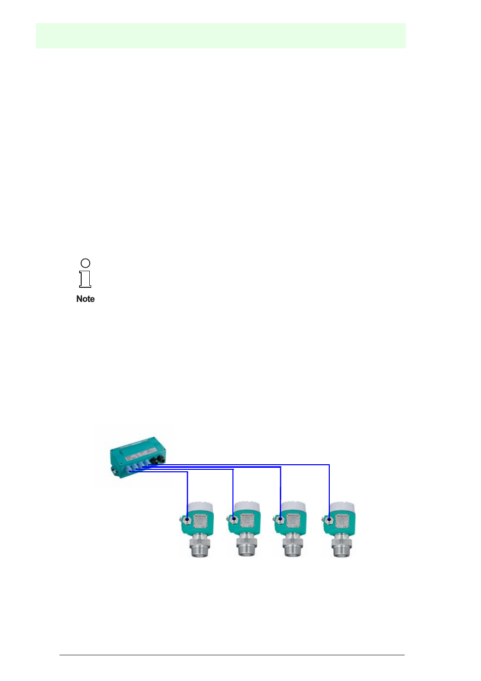
Topologies on intrinsically safe outputs
As a general rule, only one field device can be operated per FieldBarrier output. Be-
cause of the short-circuit current limiting and absence of retro-action in the FieldBar-
rier, this offers the advantage of increased system availability.
This results in the following topology of intrinsically safe outputs:
Figure 6.2: Output topology
From the point of view of the FISCO and Entity model, an output of the
FieldBarrier represents the supply source for the intrinsically safe field-
bus segment.
This opens a new, intrinsically safe fieldbus segment.