Commissioning and installation of the f2d0-fb-ex4, Fieldbarrier – VEGA FIELDBARRIER User Manual
Page 11
FieldBarrier
Subject to reasonable modifications due to technical advances.
Copyright Pepperl+Fuchs, Printed in Germany
Pepperl+Fuchs Group • Tel.: Germany +49 621 776-0 • USA +1 330 4253555 • Singapore +65 67799091 • Internet http://www.pepperl-fuchs.com
08/
2007 122329
9
4.5.1
Commissioning and installation of the F2D0-FB-Ex4.***
Only permanently laid cables and lines must be inserted into the cable glands.
The screw plugs must only be replaced by cable glands who are adapted for the in-
tended kind of use. By mounting the cable glands pay attention to the according in-
struction manual.
For the permissible cable diameters, please refer to the respective data sheet. The
operator must provide an appropriate strain-relief clamp (for example with a suitable
cable clamp). The mounting notes in chapter 4.4 must be observed.
Cable glands that are not in use must be closed off with a corresponding stop plug or
replaced by an appropriate screw plug. Stop plugs and screw plugs must have an EC
declaration of conformity.
For examples of stop plugs and screw plugs, please refer to the respective data
sheets.
For metallic housings in hazardous areas, a suitable potential equalization per EN 60
079 is required. A grounding screw is provided on the housing for this purpose. The
The ambient temperature range can be restricted by the stop plug.
By mounting the cable glands pay attention to the according instruction
manual.
In order to maintain the IP 67 protection class, all unused cable glands
(M16 and M20) must be plugged with a M20 blind plug.
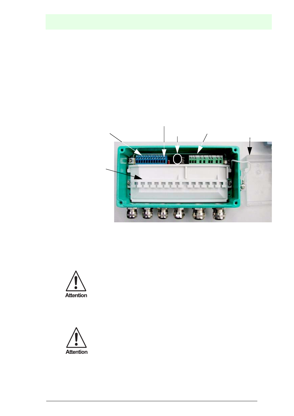
Fastening options
for connection cables
by using cable ties
Connections for
intrinsically safe
fieldbus segments
Switches for the
internal bus connection
Connections for the
non-intrinsically safe
fieldbus
Cable gland for the
non-intrinsically safe
fieldbus
Cable gland for the
intrinsically safe
fieldbus segments
Cover
LEDs