Topologies, Fieldbarrier – VEGA FIELDBARRIER User Manual
Page 17
FieldBarrier
Subject to reasonable modifications due to technical advances.
Copyright Pepperl+Fuchs, Printed in Germany
Pepperl+Fuchs Group • Tel.: Germany +49 621 776-0 • USA +1 330 4253555 • Singapore +65 67799091 • Internet http://www.pepperl-fuchs.com
08/
2007 122329
15
5.2.3
Topologies
Fieldbus topologies are independent of whether an H1 fieldbus segment of the
FOUNDATION fieldbus or a PROFIBUS MBP segment is being operated.
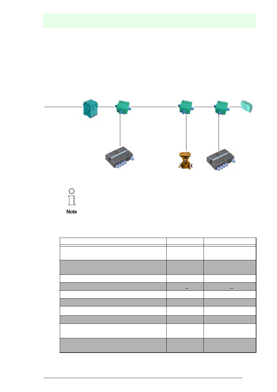
The basic layout of a fieldbus with FieldBarriers is illustrated in Figure 5.1.
Two cable types with the following components are essentially recommended for both
fieldbus systems:
The use of FieldBarriers influences possible topologies. For more
detailed information, please refer to chapter 6.2.
Type A
Type B
Cable structure
twisted wire
pair, shielded
One or more twisted
pairs, total shielding
Conductor cross-section (nominal)
0.8 mm²
(AWG 18)
0.32 mm² (AWG 22)
Loop resistor (direct current)
44
Ω/km
112
Ω/km
Wave resistance at 31.25 kHz
100
Ω + 20%
100
Ω + 30%
Wave attenuation at 39 kHz
3 dB/km
5 dB/km
Capacitive asymmetry
2 nF/km
2 nF/km
Group runtime distortion (7.9 ... 39) kHz
1.7 µs
a
a. not specified
Covering level of the shield
90%
a
Maximum extent of the network for non-
intrinsically safe applications
1900 m
1200 m
Maximum extent of the network for intrinsi-
cally safe applications
1000 m
a
Segment coupler
PROFIBUS MBP(-IS)
Bus termination
resistor
PROFIBUS DP
or
Power repeater
or H1 bus of the
FOUNDATION
fieldbus
or H1 bus (IS) of the
FOUNDATION
fieldbus
Spur
Spur
Spur
Trunk