General, Range of application of the fieldbarrier, Fieldbarrier – VEGA FIELDBARRIER User Manual
Page 14: 5general
FieldBarrier
Subject to reasonable modifications due to technical advances.
Copyright Pepperl+Fuchs, Printed in Germany
Pepperl+Fuchs Group • Tel.: Germany +49-621-776-0 • USA +1-330-4253555 • Singapore +65-67-799091 • Internet www.pepperl-fuchs.com
08/
2007 122329
12
5
General
5.1
Range of application of the FieldBarrier
FieldBarriers can be used in combination with fieldbus systems that use the "Man-
chester Coding Bus Powered“ physical layout in accordance with IEC 61158-2. This
includes the H1 bus of the FOUNDATION fieldbus and the PROFIBUS MBP, for ex-
ample. FieldBarriers ensure galvanic isolation between a non-intrinsically safe and an
intrinsically safe fieldbus segment.
The advantage of the transmission physics in accordance with IEC 61158-2 is that
power can be supplied to fieldbus stations from the transmission line. The supply cur-
rent required for this is made available by power repeaters or power supply units for
FOUNDATION Fieldbus and by the segment coupler for the PROFIBUS MBP or
PROFIBUS MBP-IS, which is intrinsically safe version of the PROFIBUS MBP.
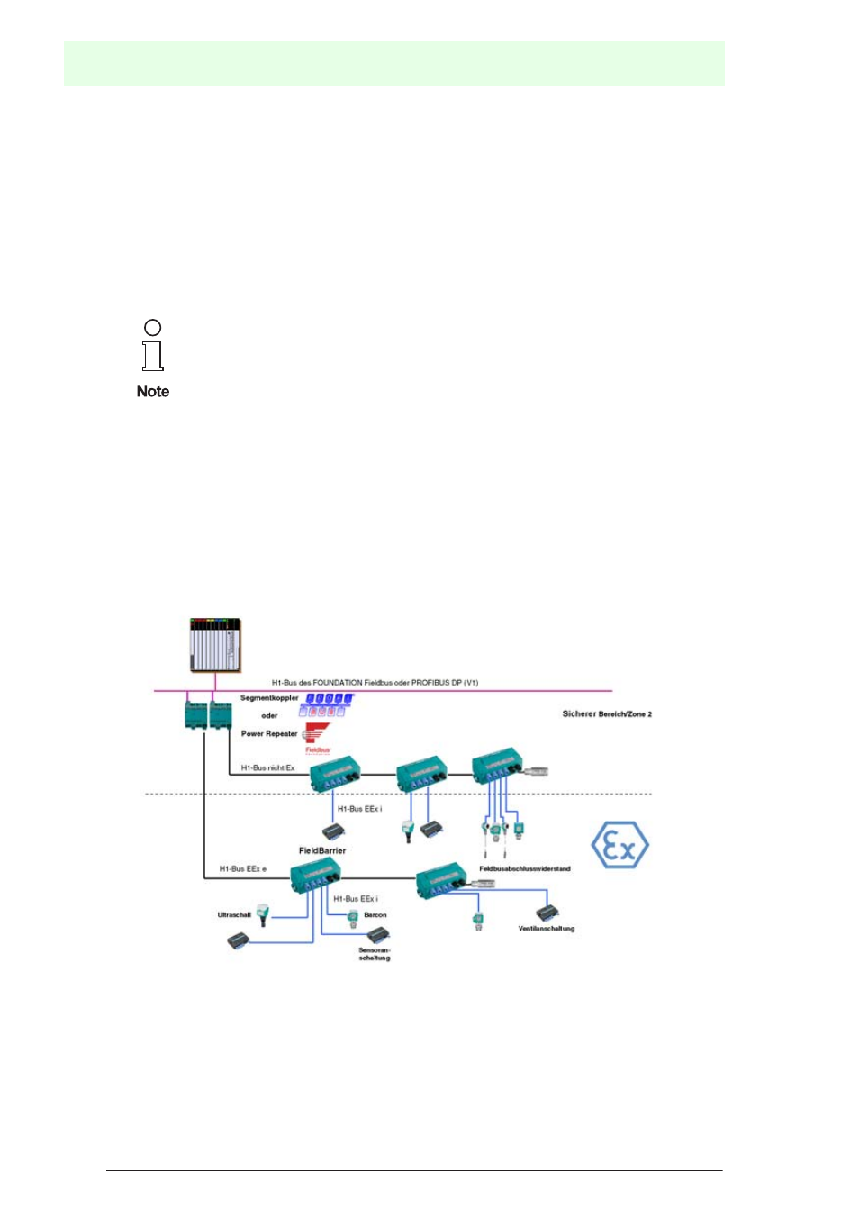
The following diagram illustrates a typical fieldbus structure in combination with Field-
Barriers
Figure 5.1: Typical field bus structure of intrinsically safe applications
5.2
Introduction to intrinsic safety for fieldbus systems
If fieldbus systems are used in hazardous areas, the corresponding explosion protec-
tion measures must be taken. The Intrinsic Safety explosion protection method offers
Both the H1 bus of the FOUNDATION fieldbus and the PROFIBUS
MBP use the physical layout described above in accordance with IEC
61158-2. The FieldBarrier can be used for both systems. When the fol-
lowing section refers to the H1 bus, this should be understood to
include both the H1 bus of the FOUNDATION fieldbus and the PROFI-
BUS MBP!