3 adjust switching delay – VEGA VEGATOR 632 User Manual
Page 33
1
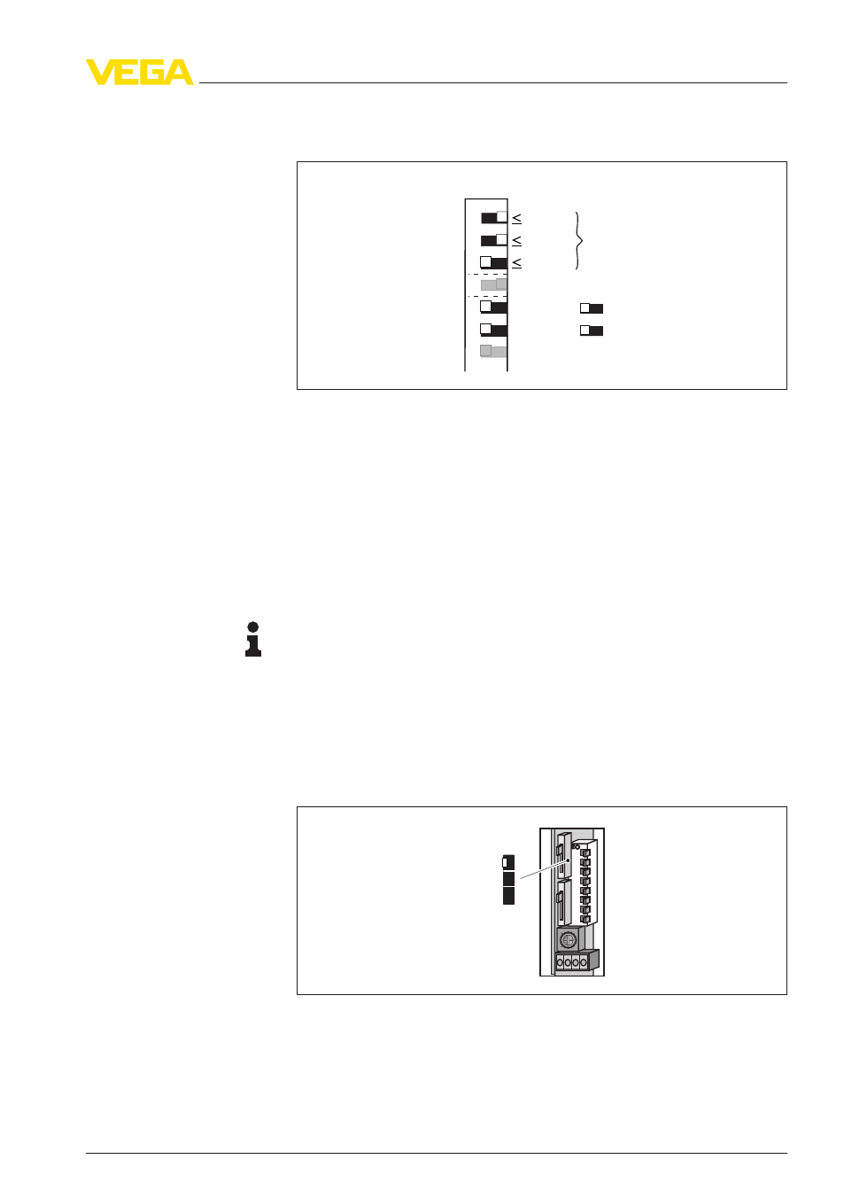
Set DIL switch 1 to 3 on the DIL switch block (A) according to the
following illustration
1 K
Ω
10 K
Ω
200 K
Ω
1 K
Ω
CH1
CH2
max.
max.
off on
1
2
3
4
5
6
7
Fig. 97: Resistance range up to 1 kΩ
2
Turn potentiometer (B) to complete left position
3
Turn potentiometer (B) slowly clockwise until the relay output
switches and the yellow control lamp changes condition
4
Turn the potentiometer approximately 15° in the same direction
If the relay output has switched, empty the vessel until the electrode is
uncovered.
The relay output must now switch again.
Note:
A failure exists, if the relay output does not switch over even in the last
range. You will find instructions for fault rectification in chapter
"M
aintenance and fault rectification".
8
.3 Adjust switching delay
Adjust the switching delay for the instrument with the slide switch (E).
O
N
3
1
3362
6 s
3 s
0,5 s
1
2
3
4
5
6
7
8
Fig. 98: Slide switch (E) for setting the switching delay
The adjusted switching delay refers to the switching function of the
relay and applies only to the switch on delay.
Adjustment of the swit-
ching delay (slide switch
E)
VEGATOR
632 • Signal conditioning instrument
33
8 Set up - Two-point control Δs (pump control)
35243
-EN
-120228