Installation, Dimensions, Installation guide current monitoring h808 – Veris Industries H808 Install User Manual
Page 2
Z201763-0F
Page 2 of 4
©2013 Veris Industries USA 800.354.8556 or +1.503.598.4564 / [email protected] 07131
Alta Labs, Enercept, Enspector, Hawkeye, Trustat, Aerospond, Veris, and the Veris ‘V’ logo are trademarks or registered trademarks of Veris Industries, L.L.C. in the USA and/or other countries.
Other companies’ trademarks are hereby acknowledged to belong to their respective owners.
Installation Guide
Current Monitoring
H808
TM
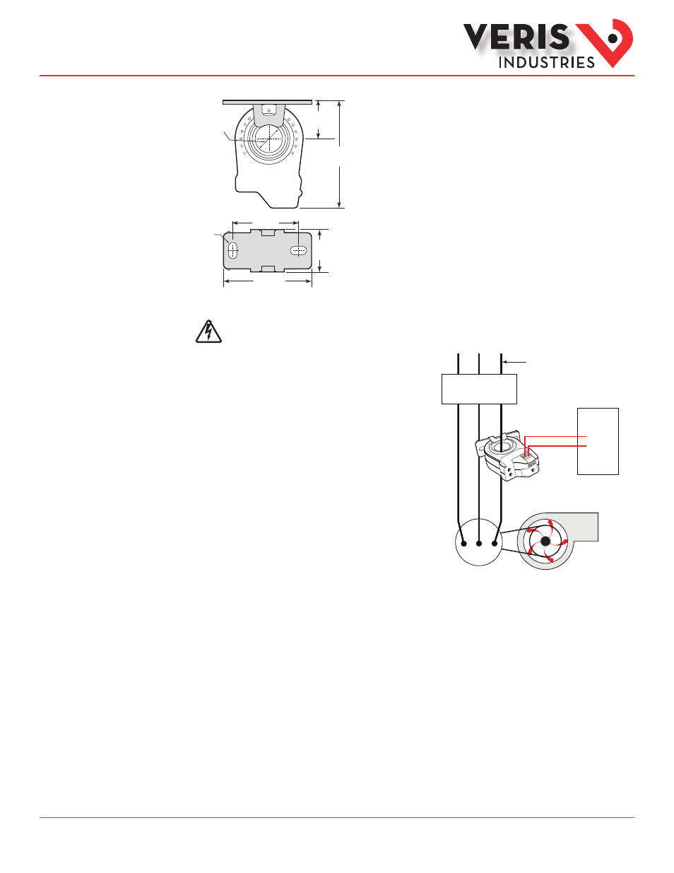
Disconnect and lock out power to the enclosure containing the conductor to be
monitored.
1. Locate a mounting surface for the removable mounting bracket
that will allow the monitored conductor to pass through the center
window when it is installed and that will keep the device at least ½”
(13 mm) from any uninsulated conductors. Determine cable routing
for the controller connection, allowing wiring to reach the mounting
location.
2. Drill holes to mount the bracket to the chosen surface using the
included screws.
3. Wire the output connections and relay between the sensor and the
controller (solid-state contact).
4. Route the conductor through the sensor’s center window and slip the
assembly into the mounting bracket.
5. Secure the enclosure and reconnect power.
6. Calibrate the sensor with the load running normally.
Installation
Motor
Fan or Pump
DDC CONTROLLER
Insulated Conductor Only
DI
CONTACTOR
0 0.7"
(18 mm)
0.4” x 0.2”
Slot (x2)
2.8"
(71 mm)
1.7
(43 mm)
2.3"
(58 mm)
1.1"
(27 mm)
0.9"
(23 mm)
Removable/Adjustable Mounting Bracket
Dimensions