Veris Industries HT SERIES Install User Manual
Ht series, Notice, Installation guide
VERIS INDUSTRIES
™
environmental SenSorS
inStallation GUiDe
Z203269-0P
PAGE 1
©2010 Veris Industries USA 800.354.8556 or +1.503.598.4564 / [email protected]
06101
Alta Labs, Enercept, Enspector, Hawkeye, Trustat, Veris, and the Veris ‘V’ logo are trademarks or registered trademarks of Veris Industries, L.L.C. in the USA and/or other countries.
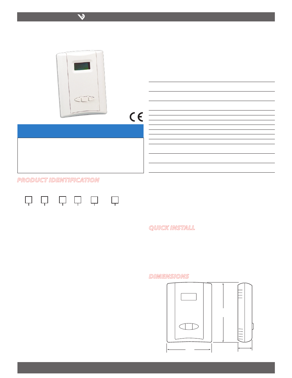
LCD Wall Mount with Analog Setpoints
1% NIST, 2% NIST, 2%, 3%, 5%
Installer’s Specifications
Input Power*
15 to 30VDC/24VAC, 100mA max.
Outputs
Switch-selectable 4-20mA or 0-10V/0-5VDC
(switch affects both outputs)
RH Sensor
Digitally profiled thin-film capacitive (32-bit mathematics)
U.S. Patent 5,844,138
Accuracy at 25°C from 10-80% RH**
±2%, 3%, or 5% models
±1% at 20-50% RH (Multi-point calibration NIST traceable)
Reset Rate***
24 hours
Stability
±1% @ 20°C (68°F) annually, for two years
Linearity
Included in Accuracy spec.
Operating Humidity Range
0-100% RH (non-condensing)
Temperature Coefficient
± 0.1%RH/°C above or below 25°C (typical)
Operating Temperature Range
10°-35°C (50°-95°F)
Temperature Accuracy
± 1.0°C ( ± 1.8°F)
Scaling
RH: 0-100% RH; Temp: 10°-35°C (50°-95°F) or
0°-50°C (32°-122°F) menu selectable
Calibration Offset
RH: Adjustable ±9.9% in 0.1% increments;
Temp: Adjustable ±5.0°C (±9.9°F) in 0.1° increments
Setpoint Range
RH: 10-80% RH in 1% increments;
Temp: Minimum to Full Scale in 1° increments
* One side of transformer secondary is connected to signal common, so an isolation transformer or
dedicated power supply may be required.
** Specified accuracy with 24VDC supplied power with rising humidity
***Reset Rate is time required to recover to 50% RH after exposure to 90% RH for 24 hours
RTD/Thermistors in wall packages are not compensated for internal heating of product.
HT SerieS
HT SerieS
Dimensions
NOTICE
• This product is not intended for life or safety applications.
• Do not install this product in hazardous or classified locations.
• Read and understand the instructions before installing
this product.
• Turn off all power supplying equipment before working on it.
• The installer is responsible for conformance to all applicable codes.
ProDuct iDentification
quick install
1. Select a mounting location away from ventilation sources. The sensor should be
mounted on a vertical wall, about 4 1/2 feet above the floor.
2. Affix the backplate to the wall.
3. Wire the device. Refer to wiring diagram.
4. Install Cover.
Setpoint
Accuracy NIST
= Analog
1 = 1%
2 = 2%
3 = 3%
5 = 5%
HT
Temp Cal
Certificate
0 = None
1 = 1 point Cal
Validation
2 = 2 point Cal
Validation
Option
B = 100R Platinum, RTD
C = 1k Platinum, RTD
D = 10k T2, Thermistor
E = 2.2k, Thermistor
F = 3k, Thermistor
G = 10k CPC Thermistor
H = 10k T3, Thermistor
J = 10k Dale, Thermistor
K = 10k w/11k with Shunt,
Thermistor
M = 20k NTC, Thermistor
N = 1800 ohm TAC, Thermistor
Q = 1uA/C, Linitemp
R = 10k US, Thermistor
S = 10k 3A 221
T = 100k, Thermistor
U = 20k “D”, Thermistor
N = NIST
(1 & 2% only)
X = No
(2, 3, 5% only)
S
= CE
1.2"
(29 mm)
3.5"
(89 mm)
4.75"
(121 mm)
-
+
Enter
A