Veris Industries CRLSxx Install User Manual
Crlsxx, Notice, Environmental co
Z205242-0B
PAGE 1
©2011 Veris Industries USA 800.354.8556 or +1.503.598.4564 / [email protected]
02113
Alta Labs, Enercept, Enspector, Hawkeye, Trustat, Veris, and the Veris ‘V’ logo are trademarks or registered trademarks of Veris Industries, L.L.C. in the USA and/or other countries.
TM
ENVIRONMENTAL SENSORS
INSTALLATION GUIDE
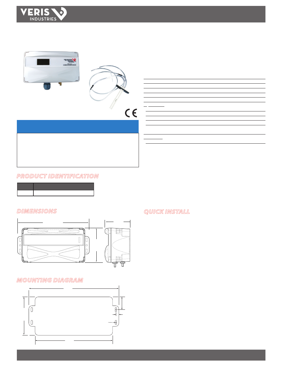
Environmental CO
2
Remote Mount Sensor
Installer’s Specifications
Input Voltage
20 to 30VDC, 24AC
Analog Output
4-20mA (clipped and capped)/0-5VDC/0-10VDC (selectable)
Sensor Current Draw
100mA max.
Operating Temperature Range
0° to 50°C (32° to 122°F)
Operating Humidity Range
0-95% (noncondensing)
Housing Material
High impact ABS plastic
CO2 Transmitter:
Sensor Type
Non-dispersive infrared (NDIR), diffusion sampling
Output Range
0-2000 ppm or 0-5000 ppm, user selectable
Accuracy
±30 ppm ±5% of measured value
Repeatability
±20 ppm ±1% of measured value
Response Time
<60 seconds for 90% step change
when
used with supplied 3 ft. sampling tube (AA50)
Relay Contacts:
1 Form C
1A@30VDC, resistive; 30W max.
EMC Conformance: EN 61000-6-4:2001 Class B, EN 61000-6-1:2001
EMC Test Methods: CISPR 11:2004, IEC 61000-4-2:2001, IEC 61000-4-3:2002, IEC
61000-4-4:2004, IEC 61000-4-5:2001, IEC 61000-4-6:2004, IEC 61000-4-8:2001, IEC
61000-4-11:2004
EMC Special Note: Connect this product to a DC distribution network or an AC/DC power
adaptor with proper surge protection (EN 61000-6-1:2001 specification requirements).
When directly measuring outside air, ensure that the air temperature reaching the sensor
is between 0° and 50°C.
Note: Rough handling and transportation may cause a temporary reduction of CO
2
sensor
accuracy. With time, the ABC function will tune the readings back to the correct accuracy range.
The default tuning speed is limited to 30 ppm per week.
CRLSxx
CRLSxx
NOTICE
• This product is not intended for life or safety applications.
• Do not install this product in hazardous or classified locations.
• Read and understand the instructions before installing
this product.
• Turn off all power supplying equipment before working on it.
• The installer is responsible for conformance to all applicable codes.
PRODUCT IDENTIFICATION
QUICK INSTALL
1. Mark and drill at least two mounting holes for the sensor.
2. Secure the sensor the the mounting surface.
3. Attach the provided pickup tubes, ensuring the supply line is connected to the
front (high) port and the return line is connected to the back (low) port.
4. Wire the device. See the Wiring section for more information.
5. Power the device.
6. Follow Configuration procedure (page 3).
CRL
AA50
MODEL
DESCRIPTION
CRLSxx
CO2 Based Remote Mount Sensor
DIMENSIONS
0.4" x 0.2"
(11mm x 5mm)
6.7"
(175 mm)
0.3"
(6 mm)
typ
1"
(26 mm)
typ
5.7"
(144 mm)
3.1"
(78 mm)
6.7"
(170 mm)
3.1"
(78 mm)
2.4"
(61 mm)
MOUNTING DIAGRAM