Installation guide, Operation, Dimensions – Veris Industries H6812 SERIES Install User Manual
Page 2
Z202815-0F
PAGE 2
©2011 Veris Industries USA 800.354.8556 or +1.503.598.4564 / [email protected]
02111
Alta Labs, Enercept, Enspector, Hawkeye, Trustat, Veris, and the Veris ‘V’ logo are trademarks or registered trademarks of Veris Industries, L.L.C. in the USA and/or other countries.
TM
H6810, H6811, H6812
INSTALLATION GUIDE
OPERATION
The H681x-V series of 1 volt and 0.333 volt split-core current transducers provide
secondary AC voltage proportional to the primary (sensed) current. For use with
power meters, data loggers, chart recorders, and other instruments, the H681x-V
series CTs provide a cost-effective means to transform electrical service amperages to
a voltage compatible with monitoring equipment.
These products provide basic insulation to 600 VAC between the sensed conductor
and the output leads. For reinforced applications, the sensed conductor must
be provided with appropriate insulation. Reinforced insulation is provided for
applications to 300 VAC between the sensed conductor and the output leads.
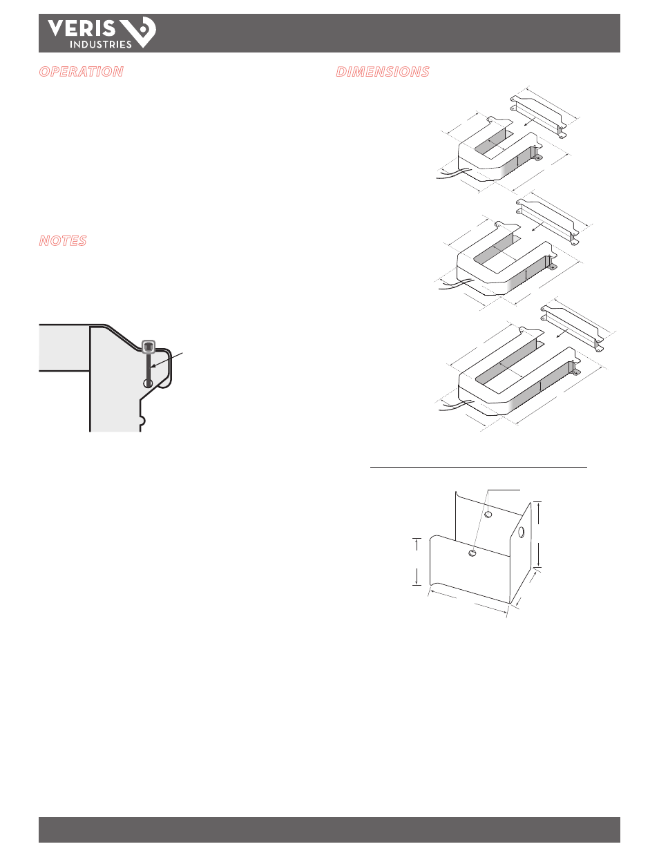
DIMENSIONS
A
B
E
F
C
D
B
E
F
C
D
A
A
B
E
C
F
D
A = 2.6" (66 mm)
B = 1.1" (28 mm)
C = 0.8" (19 mm)
D = 1" (27 mm)
E = 2.9" (74 mm)
F = 3.5" (90 mm)
A = 4.9" (124 mm)
B = 2.9" (73 mm)
C = 2.5" (62 mm)
D = 1.1" (29 mm)
E = 5.3" (141 mm)
F = 5.9" (150 mm)
A = 4.9" (124 mm)
B = 5.5" (140 mm)
C = 2.5" (62 mm)
D = 1.1" (29 mm)
E = 8.1" (207 mm)
F = 5.9" (150 mm)
H6809
200 Amp
A = 2.2" (55 mm)
B = 1.3" (33 mm)
C = 0.5" (13 mm)
D = 0.9" (24 mm)
E = 2.3" (60 mm)
F = 3.5" (90 mm)
H6806
100 Amp
H6811
400/800 Amp
A = 3.8" (95 mm)
B = 1.5" (38 mm)
C = 1.3" (32 mm)
D = 1.1" (29 mm)
E = 3.9" (107 mm)
F = 4.8" (121 mm)
H6810
100/300 Amp
H6812
800/1600/2400 Amp
A = 1.0" (26 mm)
B = 0.5" (11 mm)
C = 0.4" (10 mm)
D = 0.9" (23 mm)
E = 1.6" (40 mm)
H6802
50 Amp
D
E
C
B
A
NOTES
Accuracy is specified with the primary conductor(s) centered in the CT window.
In any application where fault currents can exceed 20 times rated current of CT, wire
ties or similar fasteners should be used to secure the I-Bar to the CT housing. Wire
ties should be used on each side of each CT (see below).
Wire ti
Wire tie used to secure I-Bar
in applications where a fault
current could exceed 20X
rated current.
Max. voltage without additional insulation: 600VAC
Do not apply current transducers to circuits having a phase-to-phase voltage greater
than the stated maximum voltage unless adequate additional insulation is applied
between the primary conductor and the current transducers. Veris assumes no
responsibility for damage of equipment or personal injury caused by transducers
operated on circuits above their published ratings.
1.3”
(34 mm)
2.5”
(64 mm)
1.3”
(34 mm)
1.8”
(45 mm)
Ø = 0.2”
(5 mm)
AH06 Mounting Bracket Dimensions (optional accessory)