Veris Industries LD1000 Install User Manual
Ld1000, L d 1 0 0 0, User guide
L D 1 0 0 0
USER GUIDE
LD1000
1. LD1000
Installation
The LD1000 is a wall mounted device, and mounting hardware is supplied with every unit. Select a location for the
LD1000 and place the two screw anchors in the wall 4.25 inches (107.9mm) apart. Screw both screws into the wall
anchors so that approximately 1/8 inch (3.18mm) of each screw is showing. (It may be necessary to adjust the
screws – in or out – so that the unit fits snugly to the wall.) Remove the front cover from the LD1000 and hang the
rear of the unit on the screws. Pull the unit toward the ground, so the screws nestle in the top of each keyhole and
securely fasten the unit to the wall. Before reattaching the front of the unit, make all wiring connections and set all
switches to the desired setting (see below for configurations).
2. Power
Connections
The LD1000 requires 24VAC or 24VDC. Make sure to wire the appropriate power to the appropriate terminal blocks
on the LD1000 to avoid damage or injury (ie DC power must only be wired to the terminal blocks labeled “DC IN”
and AC power must only be wired to the terminal blocks labeled “AC IN”). If using DC power, the power supply
must be an isolated power supply (part #WA-DC-24-ST).
3. Cable
Installation
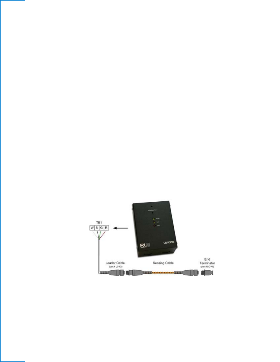
The LD1000 requires a separate leader cable (part #LC-KIT) that connects the sense cable to the unit and
terminates the line of sensing cable properly. Connect the stripped end of the 15 foot (4.57m) leader cable to the
terminal block labeled TB1 on the main board of the LD1000. From left to right, with the screws of the terminal
block connector facing up, the leader cable wires should be connected white, black, green, and red. Once the
leader cable is plugged into the terminal blocks, it is ready to be connected to the leak detection cable. To do this,
unscrew the end terminator from the end of the leader cable. Attach the first length of water leak detection cable to
the leader cable. Route the water leak detection cable according to a cable layout diagram, if provided. Secure the
end terminator on the unoccupied end of the leak detection cable.
4. Leak
Sensitivity
Adjust R25 (see diagram below) to set the desired leak sensitivity. By default, it is set to the mid-sensitivity setting
(150uA) and may be adjusted to the low (300uA) or high (25uA) sensitivity setting by turning the dial.
Dipswitch Settings
SW1-1: Configures the output relays as supervised or non-supervised. If the relays are supervised, the relays will
remain on until either power is disabled or an alarm is detected (relay will turn off). If the relays are non-supervised,
the relays will turn on upon an alarm being detected.
Off – Non-supervised (Factory Default)
On – Supervised