Dimensions, Product diagram, Installation guide current monitoring h40 series – Veris Industries H40 SERIES Install User Manual
Page 2
Z205741-0D
Page 2 of 3
©2013 Veris Industries USA 800.354.8556 or +1.503.598.4564 / [email protected] 09131
Alta Labs, Enercept, Enspector, Hawkeye, Trustat, Aerospond, Veris, and the Veris ‘V’ logo are trademarks or registered trademarks of Veris Industries, L.L.C. in the USA and/or other countries.
Other companies’ trademarks are hereby acknowledged to belong to their respective owners.
Installation Guide
Current Monitoring
H40 Series
TM
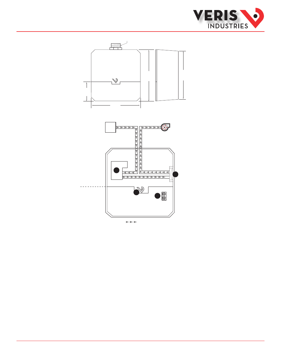
Dimensions
4.2”
(106 mm)
4.0”
(101 mm)
1/2” NPT
4.2”
(106 mm)
1.6”
(40 mm)
Product Diagram
1
2
3
= Circuit Path
Fan/Motor
Power
Source
In Series
Class 1 Voltage
Class 2 Voltage
4
1. Relay: Enables actuation of circuit by a control system
2. HOA Switch: Provides local control of the motor (H40NEXA and H40BAXA only)
HAND - When the switch is in this position, the motor is always on.
OFF - When the switch is in this position, the motor is always off.
AUTO - When the switch is in this position, the control system commands the motor.
3. Relay Coil terminal block: Wire output signal from control panel to actuate the relay.
4. Status LED:
Right side of V: Green = Coil is energized
Only the low voltage terminal blocks are accessible through the hinged lid. Other components are in the sealed high voltage compartment.