Caution, Installation guide, Operation – Veris Industries EA20 SERIES Install User Manual
Page 2: Troubleshooting, Scaling, Led indicator blink codes, Dimensions
Z206168-0B
PAGE 2
©2012 Veris Industries USA 800.354.8556 or +1.503.598.4564 / [email protected]
01122
Alta Labs, Enercept, Enspector, Hawkeye, Trustat, Veris, and the Veris ‘V’ logo are trademarks or registered trademarks of Veris Industries, L.L.C. in the USA and/or other countries.
TM
INSTALLATION GUIDE
EA20 SERIES
OPERATION
The EA20 Series of current-sensitive devices monitor DC current (amperage) in
the conductor passing through. These units use Pulse Reset Technology™ with
proven transducer circuitry to produce an output suitable for connection to energy
management systems, building controllers, or other appropriate data acquisition
equipment. The EA20 requires 12-24 VDC (see Specifications information) to generate
its output. It comes factory calibrated at a fixed span for maximum accuracy (0-100 A,
0-150 A, or 0-200 A, depending on model, see Product Identification).
The EA20 Series is ideal for DC current monitoring where accuracy must be
maintained in the presence of magnetic fields, current spikes, and high fault currents
(e.g. solar panels, electroplating equipment).
The EA20 Series housing offers unprecedented mounting flexibility. The mounting
bracket can be attached in three different places. Additionally, the bracket is
compatible with the Veris AH01 DIN Rail clip, allowing DIN mounting.
TROUBLESHOOTING
Problem
Solution
The LED is off and no signal is
produced
Verify that supply voltage is applied to PWR (+) and
GND (-) terminals.
The LED is on solid and the
output is at maximum
Verify that the unit is not attempting to monitor more
than the maximum current range.
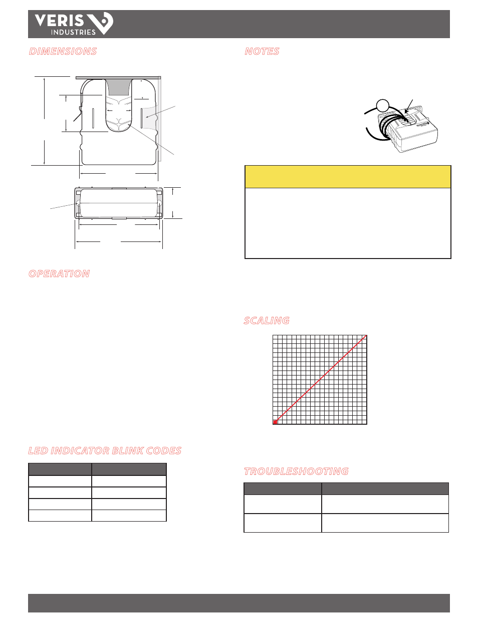
SCALING
SENSED AMPS
4 mA
100 A/150 A/200 A
(depending on model)
0 A
20 mA
SENSOR OUTPUT
LED INDICATOR BLINK CODES
LED Activity
Status Description
Single green
Normal operation
Double green
Over span
Red/green
Over limit
Solid red
Overload
DIMENSIONS
Removable Mounting Bracket
Self-gripping
Iris
1.0”
(25 mm)
0.8”
(21 mm)
1.1”
(26 mm)
3.1”
(79 mm)
2.8”
(70 mm)
Ø = 0.3”
(8 mm)
1.4”
(36 mm)
2.5”
(64 mm)
3.0”
(76 mm)
Bracket can be mounted
on three sides for added
installation flexibility.
Use DIN Rail
Mounting clip
(Veris part
number AH01) to
mount on stan-
dard DIN rail.
NOTES
Load Currents Less Than 2 A
Wrap the monitored conductor through the center window and around the sensor
body to produce multiple turns. This increases
the current measured by the transducer.
Program equipment to account for the extra
turns, e.g., if four turns pass through the sensor
(as shown) then divide the reading by 4.
Wrapping may reduce the sensor’s accuracy.
4x
1A
CAUTION
RISK OF EQUIPMENT DAMAGE
• Derate the product’s maximum current for the number of turns
through the sensing window using the following formula.
Rated Max. Amps ÷ Number of Turns = Max. monitored Amps
e.g. : 100A ÷ 4 Turns = 25 Amps max. in monitored conductor
• Failure to follow these instructions can result in overheating
and permanent equipment damage.
High Load Current Monitoring
Do not expose the EA20 to continuous current levels greater than the rated maximum
current (brief current surges and fault currents should not adversely affect the EA20).