Veris Industries EA20 SERIES Install User Manual
Ea20 series, Notice, Danger
TM
CURRENT MONITORING
INSTALLATION GUIDE
Z206168-0B
PAGE 1
©2012 Veris Industries USA 800.354.8556 or +1.503.598.4564 / [email protected]
01122
Alta Labs, Enercept, Enspector, Hawkeye, Trustat, Veris, and the Veris ‘V’ logo are trademarks or registered trademarks of Veris Industries, L.L.C. in the USA and/or other countries.
Split-Core Uni-Directional 4-20 mA Output
DC Current Transducer
HAZARD OF ELECTRIC SHOCK, EXPLOSION, OR ARC FLASH
• Follow safe electrical work practices.
See NFPA 70E in the USA, or applicable local codes.
• This equipment must only be installed and serviced by qualified electrical personnel.
• Read, understand and follow the instructions before installing this product.
• Turn off all power supplying equipment before working on or inside the equipment.
• Use a properly rated voltage sensing device to confirm power is off.
DO NOT DEPEND ON THIS PRODUCT FOR VOLTAGE INDICATION
• Only install this product on insulated conductors.
Failure to follow these instructions will result in death or serious injury.
DANGER
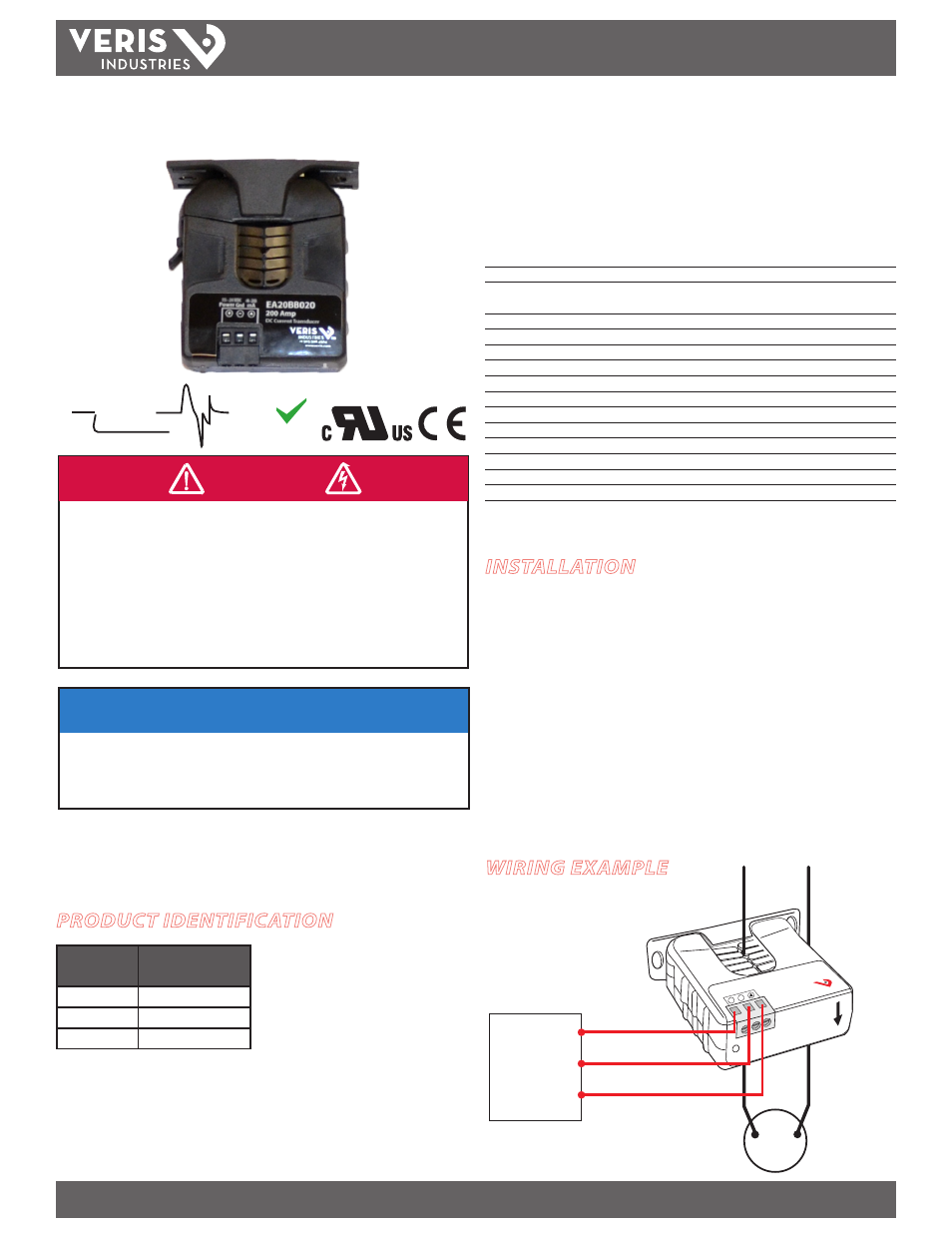
WIRING EXAMPLE
EA20 SEriES
EA20 SEriES
NOTICE
• This product is not intended for life or safety applications.
• Do not install this product in hazardous or classified locations.
• The installer is responsible for conformance to all applicable codes.
• Mount this product inside a suitable fire and electrical enclosure.
pulse reset
technology™
U.S. Pat. #6,160,697; 6,522,517; 7,242,157
Installer’s Specifications
Technology
Exclusive Pulse Reset Technology™
Amperage Range for Stated Accuracy
0.5A to 100, 150, or 200ADC
Sensor Supply Voltage
12 to 24VDC (for currents over 120A,
supply
voltage must be at least 15V)
Supply Current
35mA to 110mA*
Insulation Class
1000VDC (insulated conductor)
Temperature Range -30° to 60°C (-22° to 140°F)
Humidity Range
10-90% RH non-condensing
Output
4-20mA
Accuracy
±0.5% full scale, combined linearity, hysteresis, and repeatability
Withstand Current
Up to 25,000ADC continuous
Terminal Block Maximum Wire Size
14 AWG
Terminal Block Torque (nominal)
4 in-lbs (0.45 N-m)
Rated Altitude
2000 m
Pollution Degree 2
Installation Category III
* At zero load current: 35 mA; at maximum load current: 55 mA to 110 mA, depending on supply
voltage.
INSTALLATION
1. Disconnect and lock out power to the conductor to be monitored.
2. Choose a location for the sensor. The monitored conductor must pass through the
iris, and the sensor must be at least 1/2” from any conductors, as enclosure can
reach 87°C during operation (at 200A and 60°C ambient temperature). Use wire
rated at a minimum of 90°C.
3. Install the adjustable mounting bracket to the back of the enclosure using the
included screws.
4. Connect 12-24 VDC to the terminals marked Power (+) and Gnd (-).
5. Wire the mA output connections between the sensor and the controller.
6. Snap the sensor over the conductor to be monitored and clip the assembly to the
mounting bracket.
DIGITAL CONTROL
Gnd
4-20 mA input
DC
Load
Power (12-24VDC)
Power
Gnd
4-20
mA
12–24 VDC
–
+
To
Load
RoHS
Compliant
PRODUCT IDENTIFICATION
MODEL
AMPERAGE RANGE
(DC)
EA20BB010
0-100 A
EA20BB015
0-150 A
EA20BB020
0-200 A
For use in a Pollution Degree 2 or better environment only. A Pollution Degree 2 environment must
control conductive pollution and the possibility of condensation or high humidity. Consider the
enclosure, the correct use of ventilation, thermal properties of the equipment, and the relationship
with the environment. Installation category: CAT II or CAT III