Installation guide, Wiring & configuration, Jumper configuration – Veris Industries EP2 SERIES Install User Manual
Page 2: Options, Terminal block connections
Z203044-0U
PAGE 2
©2012 Veris Industries USA 800.354.8556 or +1.503.598.4564 / [email protected]
07121
Alta Labs, Enercept, Enspector, Hawkeye, Trustat, Veris, and the Veris ‘V’ logo are trademarks or registered trademarks of Veris Industries, L.L.C. in the USA and/or other countries.
TM
EP2
inStallation GUiDE
WirinG & confiGuration
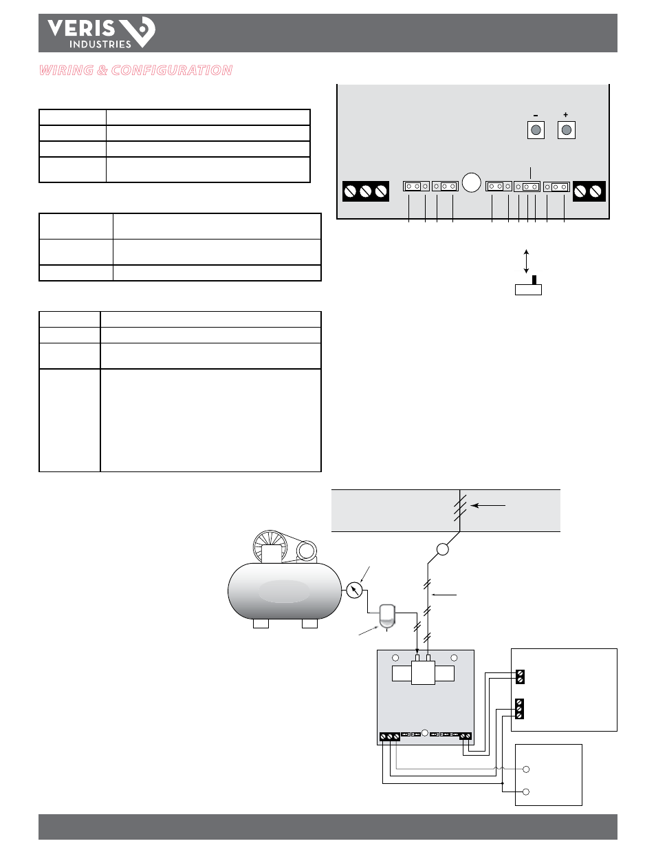
Jumper Configuration
Input
Current (4-20 mA) or Voltage (0-5 V or 0-10 V)
Voltage
For voltage mode of operation, select 0-5 V or 0-10 V
Pressure Range
Select 0-20 psi or 3-15 psi scaling
Operation Mode
Select AUTO for normal operation or MANUAL to adjust pressure
using the pushbuttons
Options
Alarm Mode Relay
The alarm contacts open if the EP2 cannot obtain 80% of
commanded pressure within two (2) minutes
Manual Mode Alarm
Contacts open when manual mode is selected (auto mode contacts
are closed)
Vent On Power Fail
The EP2 vents the branch line pressure on power failure
Terminal Block Connections
GND/Common
Power supply ground and signal common.
Input Signal
4-20 mA, 0-10 VDC, or 0-5 VDC input from the control system.
Power
22-30 VDC, 20-30 VAC. From the control system or external power
supply or transformer.
Pressure Loss
Alarm (optional)
Normally closed, solid-state contacts open if the main supply pressure
fails or if the transducer is otherwise unable to produce the correct
branch pressure. Connect to the digital input of the control system for
alarm status indication. If commanded pressure does not reach 80%
within 2 minutes, the alarm contacts open.
• 0-20 psi alarm contact does not change state when the
commanded pressure is 4 psi or less
• 3-15 psi alarm contact does not change state when the
commanded pressure is 5.4 psi or less
NOTE: In 24 VAC transformer applications, one side of the transformer secondary is connected to
the signal common. Some control systems may require a dedicated power supply transformer or
isolation transformer.
ALARM
MODE
MANUAL ADJUST
ON
OFF
Aut
o
Mode
M
anual
0-20psi
3-15psi
0-5V
0-10V
Curr
ent
Voltage
GND/C
OM
INPUT SIGNAL
POWER
PRESSURE
RANGE
PRESSURE
LOSS
ALARM
(OPTIONAL)
OPERATION
MODE
INPUT
MODE
VOLTAGE
MODE
SLIDE
SWITCH
OPTION
AVAILABLE
GND INPUT POWE
R
DIGIT
AL IN
DIGITAL INPUT
(CONTACT CLOSURE)
ANALOG OUT (0-5/0-10, 4-20mA)
COMMON
20-45 PSI OUT
REGULATOR
DUCT
DAMPER
TO DAMPER
TRAP/FILTER
PRESSURE L
OSS ALARM
POWER SUPPLY
24VAC/DC
VERIS PS-24 Series
CONTROL PANEL
AIR COMPRESSOR
EP21XX
+
-