Veris Industries EP2 SERIES Install User Manual
Notice, Electropneumatic transducer, Installation guide
Z203044-0U
PAGE 1
©2012 Veris Industries USA 800.354.8556 or +1.503.598.4564 / [email protected]
07121
Alta Labs, Enercept, Enspector, Hawkeye, Trustat, Veris, and the Veris ‘V’ logo are trademarks or registered trademarks of Veris Industries, L.L.C. in the USA and/or other countries.
TM
EnvironmEntal SEnSorS
inStallation GUiDE
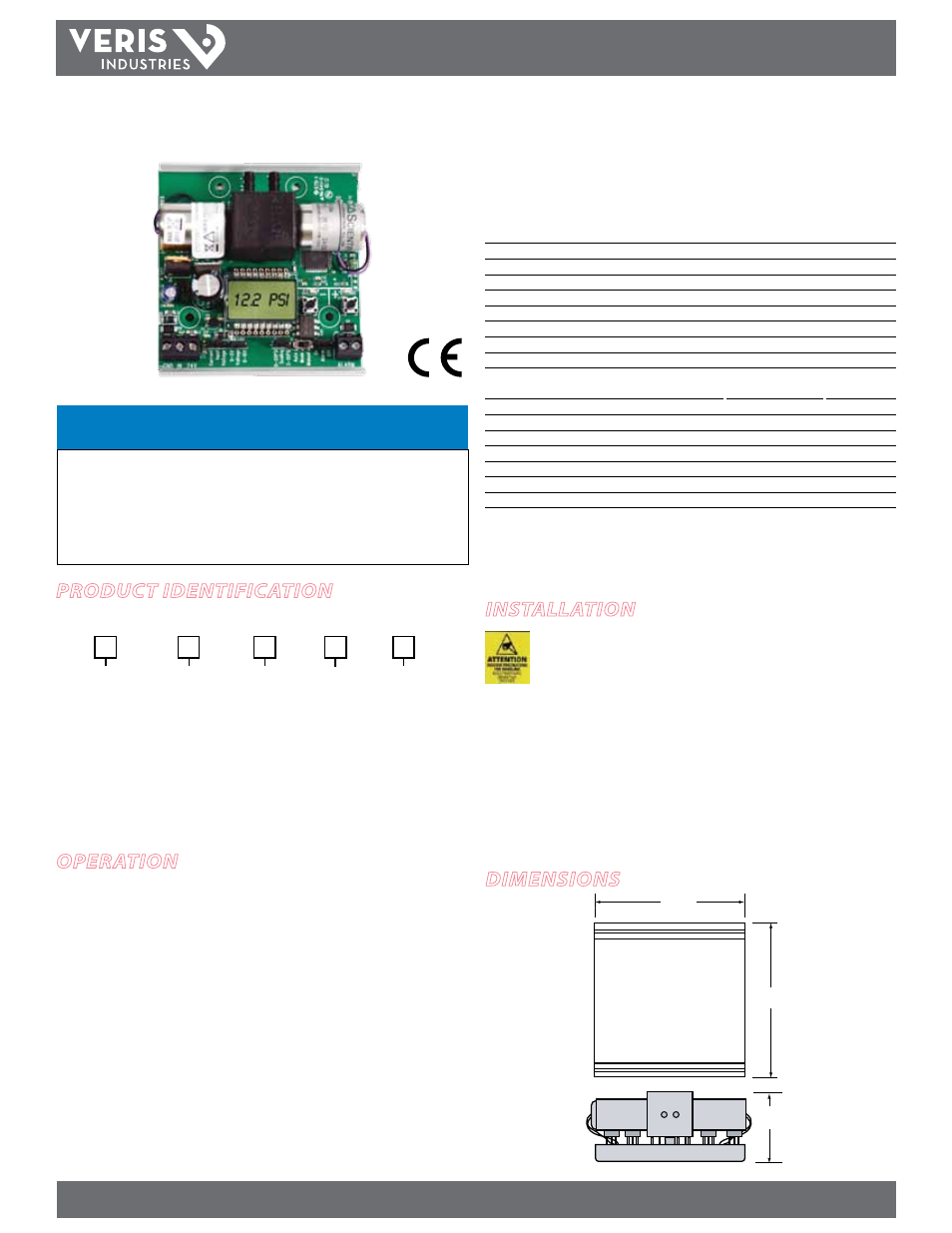
Electropneumatic Transducer
Installer’s Specifications
Power Supply
22-30VDC, 20-30VAC, 47-63 Hz, 150mA max.
Control Input
4-20mA, 0-10V, 0-5V; jumper selectable
Input Impedance
4-20mA, 250 Ω; 0-5/0-10V, 10 kΩ
Manual Override
Jumper selectable mode, digital pushbutton adjust
Alarm Contact
100mA@30VAC/DC (If equiped)
Accuracy
1% full scale; combined linearity, hysteresis, repeatability
Compensated Temperature Range
-4°C to 60°C (25° to 140°F)
Temp Coefficient ±0.05%/°C
Operating Environment
10-90% RH, non-condensing; -4°C to 60°C (25° to 140°F)
SCIM
523 in
3
/min.@45 psi; 8520 cm
3
/[email protected] kPA;
333
in
3
/min@20 psi; 5407 cm
3
/[email protected] kPA
Supply Pressure
45 psig max.
Control Range
0-20 psig or 3-15 psig jumper selectable
Pressure Differential
0.1 psig (supply to branch)
Pressure Indication
Electronic, 3-1/2 digit LCD
Minimum Tubing Length
15 feet
Port Connection
1/8” i.d. poly tubing
Media Connection
Clean dry air or inert gas. Not for use with oxygen service
EMC Conformance: EN 61000-6-3:2007 and A1:2011 Class B, EN 61000-6-1:2007
EMC Special Note: Connect this product to a DC distribution network or an AC/DC power adaptor
with proper surge protection (EN 61000-6-1:2007 specification requirements)
EP2
EP2
Dimensions
NOTICE
• This product is not intended for life or safety applications.
• Do not install this product in hazardous or classified locations.
• Read and understand the instructions before installing
this product.
• Turn off all power supplying equipment before working on it.
• The installer is responsible for conformance to all applicable codes.
ProDuct iDentification
installation
Observe precautions for handling static sensitive
devices to avoid damage to the circuitry that
is not covered under the factory warranty.
1. Mount the transducer using the screws provided. Avoid damaging the electronic
components.
2. Wire the transducer and configure the jumpers for desired operation as shown in
the Wiring and Configuration section on the following page.
4. Attach pressure tubing to the hose barbs. Observe MAIN and BRANCH port labels.
Use flexible ¼” O.D. poly tubing for the main and branch pneumatic connections.
Main supply pressure must not exceed 45 psig.
1.9"
(48 mm)
3.3"
(84 mm)
3.5"
(89 mm)
Output
= Selectable
3-15/0-20 psi
US or EU
S = Standard
C = CE (in-
cludes cover
plate.)
Feedback
0 = None
1 = Pressure
Loss Alarm
2 = Manual
Mode Alarm
EP2
Failsafe
0 = None
1 = Vent on
Power Fail
Option
Blank = none
1 = Slide Switch/
Auto/Manual
2 = EP Cover Plate
3 = Slide Switch/
Auto Manual plus
EP cover plate
1
available
oPeration
The EP2 electropneumatic pressure transducer uses micro-controlled poppet valve
technology for highly accurate pressure sensing. The poppet valves consume no air,
eliminating unnecessary air losses in the system and allowing for stable and reliable
operation. The EP2 is comes installed on standard SnapTrack, and an optional cover
is available to protect from dust and other environmental factors. An LCD display and
LED indicators make it easy to read system status at a glance.