Veris Industries H280 Install User Manual
Notice, Danger, Load status switch
TM
CURRENT MONITORING
INSTALLATION GUIDE
Z203739-0A
PAGE 1
©2012 Veris Industries USA 800.354.8556 or +1.503.598.4564 / [email protected]
01121
Alta Labs, Enercept, Enspector, Hawkeye, Trustat, Veris, and the Veris ‘V’ logo are trademarks or registered trademarks of Veris Industries, L.L.C. in the USA and/or other countries.
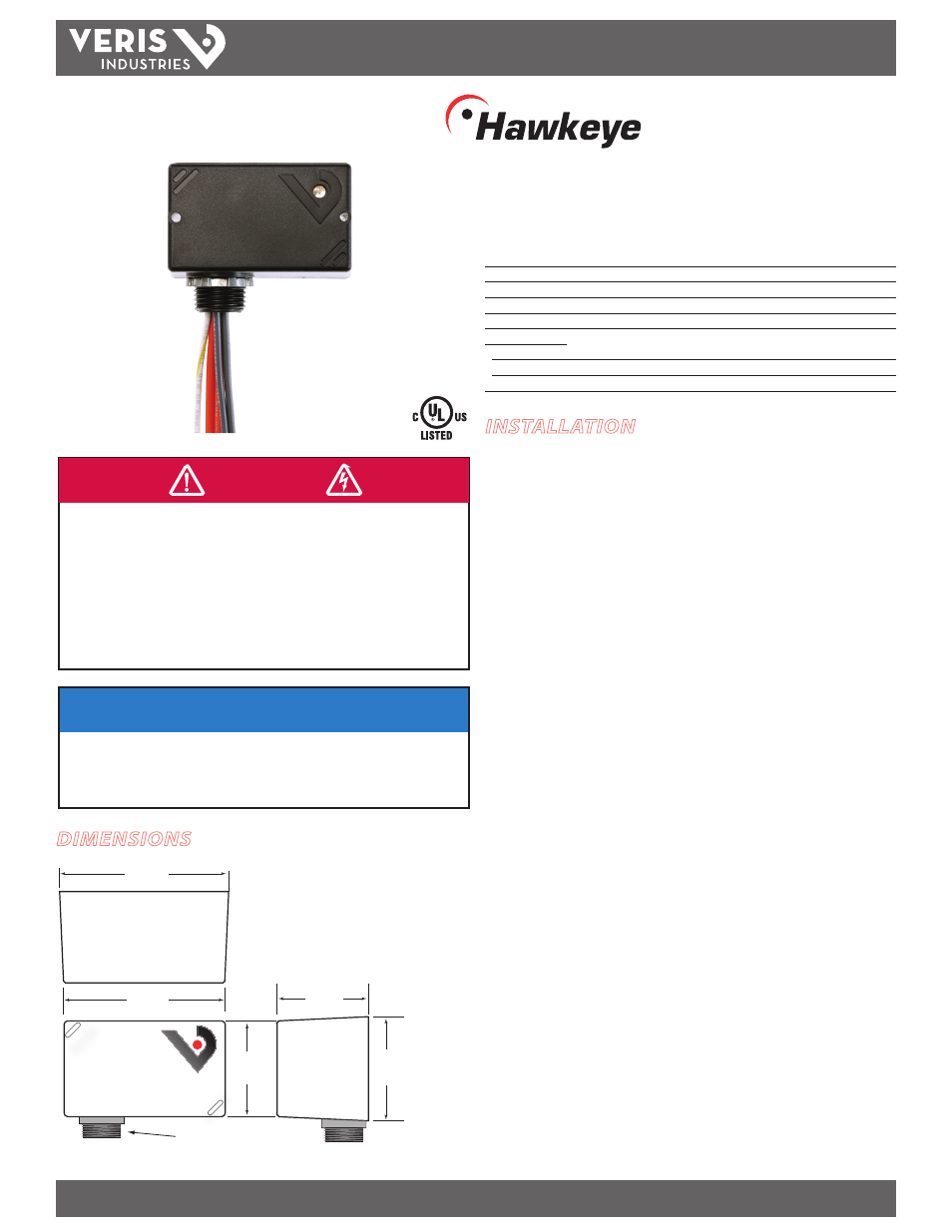
Load Status Switch
Installer’s Specifications
Sensor Power
Line powered
Operating Temperature
-15° to 60°C (5° to 140°F)
Operating Humidity
10-90% RH, non-condensing
LED Status
GREEN LED=status normal; RED LED=status alarm
Frequency
50/60 Hz
Wire Specifications:
Lead Length
14”(356mm) min.
Gauge
UL1015; Neutral: 18AWG; Line: 12AWG; Status: 16AWG
Agency Approvals
UL 508, E150462
HAZARD OF ELECTRIC SHOCK, EXPLOSION, OR ARC FLASH
• Follow safe electrical work practices.
See NFPA 70E in the USA, or applicable local codes.
• This equipment must only be installed and serviced by qualified electrical personnel.
• Read, understand and follow the instructions before installing this product.
• Turn off all power supplying equipment before working on or inside the equipment.
• Use a properly rated voltage sensing device to confirm power is off.
DO NOT DEPEND ON THIS PRODUCT FOR VOLTAGE INDICATION
Failure to follow these instructions will result in death or serious injury.
DANGER
H280, H280NC
TM
280, 280NC
DIMENSIONS
NOTICE
• This product is not intended for life or safety applications.
• Do not install this product in hazardous or classified locations.
• The installer is responsible for conformance to all applicable codes.
• Mount this product inside a suitable fire and electrical enclosure.
INSTALLATION
Disconnect and lock out all power sources before beginning the
installation.
1. Using the threaded nipple, connect the switch to the desired enclosure through a
knock out hole.
2. Secure with the conduit nut provided.
3. Connect load in series:
• Choose one orange wire and connect to load side of switch.
• Choose the other orange wire and connect to load.
4. Connect status output:
• Connect the grey wires (or brown wires for H280NC) to controller digital
input. Not polarity sensitive.
5. Secure the enclosure and reconnect power.
Wires that are not terminated must be isolated or insulated, i.e. wire nut.
1.6"
(41 mm)
1.7"
(43 mm)
1/2" NPT Nipple
1.8"
(46 mm)
2.9"
(74 mm)
2.8"
(71 mm)