F. measuring diodes, Instrument set-up, Measurement procedure – Test Products International 440 User Manual
Page 21: Optional dmm functions (refer to page 27)
22
20
f.
Measuring Diodes
CAUTION!
Do not attempt to make diode measurements with circuit
energized. The only way to accurately test a diode is to
remove it completely from the circuit before attempting to
measure it.
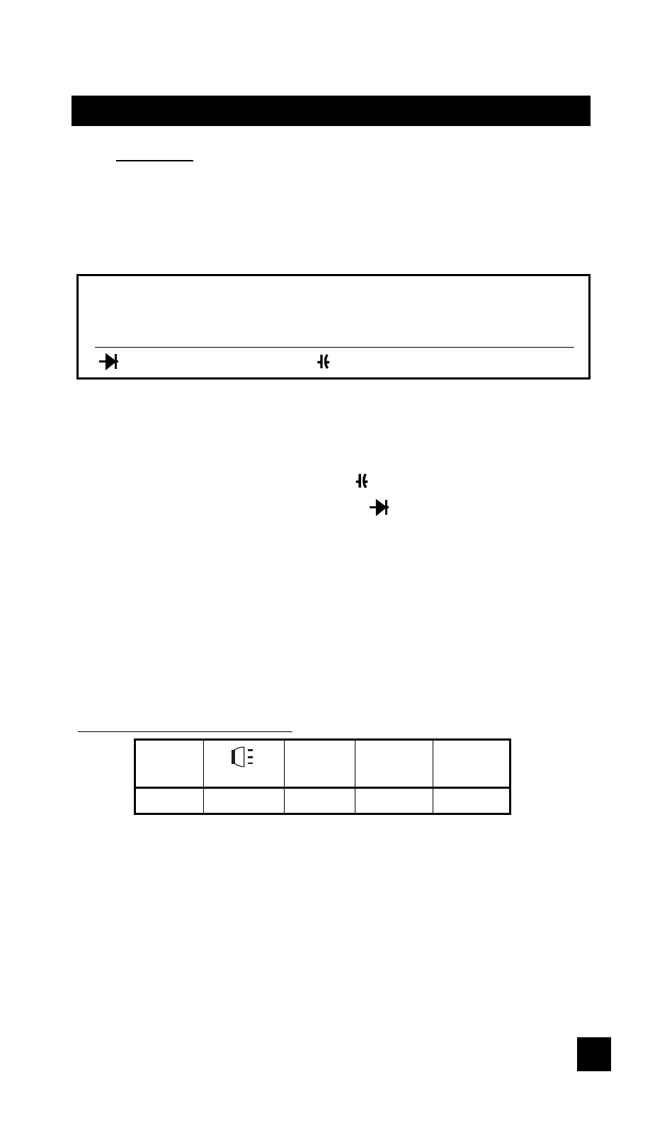
Instrument set-up:
FUNCTION
BLACK RED
MINIMUM
MAXIMUM
TEST LEAD
TEST LEAD
READING
READING
COM
V
Ω
0.001V
2.000V
Measurement Procedure:
1.
Disconnect power to circuit to be measured.
2.
Plug black test lead into the COM input jack.
3.
Plug red test lead into V
Ω
input jack.
4.
Set the rotary switch to the
function.
5.
Connect black test lead to the banded end of the diode
and the red test lead to the non-banded end of the diode.
6.
Reading on display should be between 0.5 and 0.8 volts.
7.
Reverse test lead connections in 5 above.
8.
Reading on the display should be OUCH (Overload).
NOTE: If diode reads 0 in both directions, diode is shorted.
If diode reads OUCH in both directions, diode is open.
Optional DMM Functions (refer to page 27)
POLA.
CHECK
F1
F2
F3
F4
F5