Installation guide, Operation, Ratings – Veris Industries H681x-5A SERIES Install User Manual
Page 2: Accuracy, Dimensions, H681x-5a series
Z201970-0G
PAGE 2
©2012 Veris Industries USA 800.354.8556 or +1.503.598.4564 / [email protected]
05121
Alta Labs, Enercept, Enspector, Hawkeye, Trustat, Veris, and the Veris ‘V’ logo are trademarks or registered trademarks of Veris Industries, L.L.C. in the USA and/or other countries.
TM
H681x-5A SERIES
INSTALLATION GUIDE
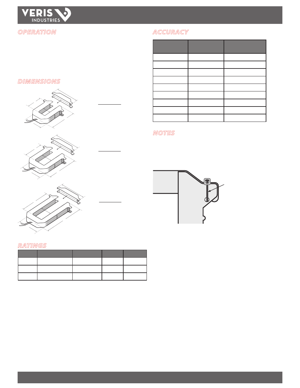
NOTES
Accuracy is specified with the primary conductor(s) centered in the CT window.
In any application where fault currents can exceed 20 times rated current of CT, use
wire ties or similar fasteners to secure the I-bar to the CT housing (see below). Secure
both sides of the I-bar.
Wire ti
Secure I-bar with a wire tie
in applications where a fault
current could exceed 20x
rated current.
Max. voltage without additional insulation: 600VAC for the H6810, H6811, and H6812
Do not apply current transformers to circuits having a phase-to-neutral voltage
greater than the stated maximum voltage unless adequate additional insulation is
applied between the primary conductor and the current transformers. Veris assumes
no responsibility for damage of equipment or personal injury caused by transformers
operated on circuits above their published ratings.
OPERATION
The H681x-xxx series of 5 Amp split-core current transformers provide secondary
amperage proportional to the primary (sensed) current. For use with power meters,
data loggers, chart recorders, and other instruments, the H681x Series 5 Amp CTs
provide a cost-effective means to transform electrical service amperages to a 0 to 5
Amp level compatible with monitoring equipment.
RATINGS
Model
Sensing Current (A)
Frequency (Hz)
Output (A) Weight (kg)
H6810
0 to 300
50/60
0 to 5
0.340
H6811
0 to 800
50/60
0 to 5
0.580
H6812
0 to 2400
50/60
0 to 5
0.870
These products provide basic insulation to 600 VAC between the sensed conductor
and the output leads. For reinforced applications, the sensed conductor must
be provided with appropriate insulation. Reinforced insulation is provided for
applications to 300 VAC between the sensed conductor and the output leads.
ACCURACY
Model #
Accuracy from 10%
to 100% of CT Rating
Burden Capacity (VA)
H6810-200A-5A
1%
2.5
H6810-300A-5A
1%
2.5
H6811-400A-5A
1%
5.0
H6811-600A-5A
1%
5.0
H6811-800A-5A
1%
12.5
H6812-800A-5A
1%
5.0
H6812-1200A-5A
1%
22.5
H6812-1600A-5A
1%
22.5
H6812-2400-5A
1%
22.5
DIMENSIONS
A
B
E
F
C
D
B
E
F
C
D
A
A
B
E
C
F
D
H6810
SMALL (SIZE 2)
200/300 Amp
H6811
MEDIUM (SIZE 3)
400/600/800 Amp
H6812
LARGE (SIZE 4)
800/1600/2400 Amp
A =
3.8" (96 mm)
B =
1.2" (30 mm)
C =
1.3" (31 mm)
D =
1.2" (30 mm)
E =
4.0" (100 mm)
F =
4.8" (121 mm)
A =
4.9" (125 mm)
B =
2.9" (73 mm)
C =
2.5" (62 mm)
D =
1.2" (30 mm)
E =
5.2" (132 mm)
F =
6.0" (151 mm)
A =
4.9" (125 mm)
B =
5.5" (139 mm)
C =
2.5" (62 mm)
D =
1.2" (30 mm)
E =
7.9" (201 mm)
F =
6.0" (151 mm)