Veris Industries H681x-5A SERIES Install User Manual
H681x-5a series, Notice, Danger
Z201970-0G
PAGE 1
©2012 Veris Industries USA 800.354.8556 or +1.503.598.4564 / [email protected]
05121
Alta Labs, Enercept, Enspector, Hawkeye, Trustat, Veris, and the Veris ‘V’ logo are trademarks or registered trademarks of Veris Industries, L.L.C. in the USA and/or other countries.
TM
POWER MONITORING
INSTALLATION GUIDE
H6810, H6811,
H6812
Installer’s Specifications
Output at Rated Current
5 Amps AC
Accuracy
see table (page 2)
Leads
18 AWG, UL 1015 twisted pair, 6’ (1.8 m) standard length
Operating Temperature Range
-15° to 60°C (5° to 140°F)
Storage Temperature Range
-40° to 70°C (-40° to 158°)
Humidity Range
0-95% noncondensing
Max. Voltage L-N Sensed Conductor
600 VAC (basic insulation rating)
Frequency Range
50/60 Hz
Altitude of Operation
3km max.
Installation Category
Cat II or Cat III
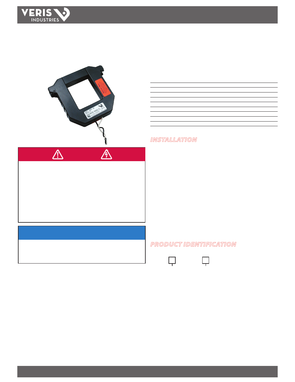
5 Amp Split-Core Current Transformers
HAZARD OF ELECTRIC SHOCK, EXPLOSION, OR ARC FLASH
• Follow safe electrical work practices.
See NFPA 70E in the USA, or applicable local codes.
• This equipment must only be installed and serviced by qualified electrical personnel.
• Read, understand and follow the instructions before installing this product.
• Turn off all power supplying equipment before working on or inside the equipment.
• Use a properly rated voltage sensing device to confirm power is off.
DO NOT DEPEND ON THIS PRODUCT FOR VOLTAGE INDICATION
• SECONDARY LEADS/TERMINALS OF CURRENT OUTPUT (e.g. 5A) CTs MUST BE SHORTED,
OR CONNECTED TO THE BURDEN AT ALL TIMES.
Failure to follow these instructions will result in death or serious injury.
DANGER
NOTICE
• This product is not intended for life or safety applications.
• Do not install this product in hazardous or classified locations.
• The installer is responsible for conformance to all applicable codes.
• Mount this product inside a suitable fire and electrical enclosure.
PRODUCT IDENTIFICATION
INSTALLATION
1. Disconnect and lock out power to the primary circuit before installing these
current transducers (CTs).
2. Connect the secondary leads to the burden or test switching/shorting bar. The
white wire is the X1 lead.
3. Depress the tabs on one end of the current transformer to open it and slip it over
the primary leads. Note labeling on product indicating “source side.”
4. Check the core ends on both sections of the CT to assure there is no rust or debris in
the closure areas.
5. Close and latch the CT, and mount it securely.
6. Reconnect power to the panel.
Optional mounting kit available for the H6810, H6811, and H6812. See Veris AH06.
H681x-5A SERIES
H681
Model/Amps
Small:
0-200 = 200A
0-300 = 300A
Medium:
1-400 = 400A
1-600 = 600A
1-800 = 800A
Large:
2-800 = 800A
2-1000 = 1000A
2-1200 = 1200A
2-1600 = 1600A
2-2000 = 2000A
2-2400 = 2400A
-
Output Type
= 5 Amp
5A