Veris Industries Badger 228 SERIES Install User Manual
Page 8
8
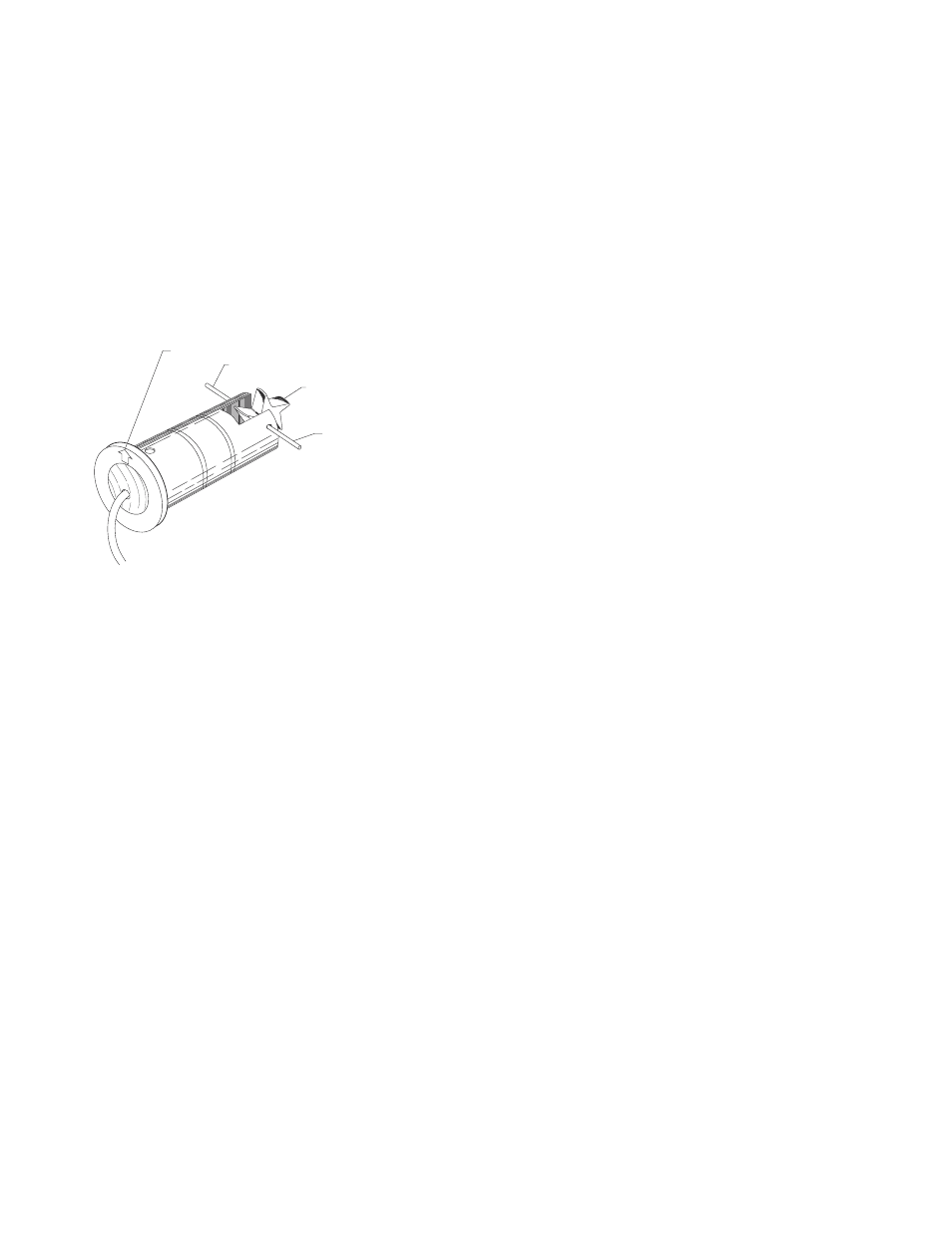
ing holes on metal sensors. For 250B the flow direc-
tion arrow on the top of the sensor housing should
point downstream with the impeller blades pointing
upstream.
8) Carefully push the shaft through the sleeve and
impeller, taking care not to damage bearings. Make
sure that the shaft is inserted far enough so that it
clears the sleeve on each side of the impeller hous-
ing.
nOTE: If shaft is not carefully installed, the bearing
can be deformed, preventing free rotation.
9) Inspect the O-rings for damage and replace as
necessary. Clean the O-rings and the sleeve and lu-
bricate with silicone grease from the packet provided
or some other acceptable lubricant.
NOTE DIRECTION OF ARROW
USE PLIERS HERE
NOTE DIRECTION OF
IMPELLER
USE METAL PIN TO
REMOVE CERAMIC SHAFT
Figure 1
Impeller Assembly and Shaft Replacement
10) Install the sensor into the 2” NPT adapter or tee so
that alignment hole is facing upstream and flow ar-
rows point in the direction of the actual flow. Since
the positioning collar was not loosened during this
operation, the studs should all line up perfectly when
the sighting holes are parallel to pipe. If this has
been accidentally loosened, please refer to the instal-
lation instructions for the alignment of the flow sensor
unit.
11) Install and tighten the nuts or replace the clevis pin.
12) For metal sensors, double check that the distance
from the top of the 2” NPT adapter to the bottom
of the positioning collar equals the dimension as
measured in Step 2, and holes in sleeve sight exactly
down the pipe, the arrows point in direction of flow
and alignment holes located beside one sighting hole
is pointing towards the source. If not, refer to Installa-
tion section in this manual.
13) This completes the replacement procedure. The
system may now be repressurized and tested.